Planimeter and zero circle Planimeter The area of


 A planimeter is a precise instrument which measures the area of plan of")


 Where F=final reading I=initial reading M= A multiplying constant. It is equal to")

 C= 24. 686")

 Ø By using formula: (a)Area of zero circle= M C Where M= multiplier")

 Solution: Here , M=100 , I=8. 596 , F = 4. 149 ,")
")

- Slides: 17
Planimeter and zero circle
Planimeter The area of the land in plane surveying is determined by various methods. This area is determined by a particular method is used for many purposes such as to determine the quantities of earthwork , fixing the boundary of the field and thus calculating the area based upon which the revenue is paid. The metric units of area are Sq. mt. or hectares.
(continue) A planimeter is a precise instrument which measures the area of plan of any shape with more accuracy. There are two types of planimeter: 1. Amsler polar planimeter 2. Roller planimeter The most commonly used type is the polar planimeter.
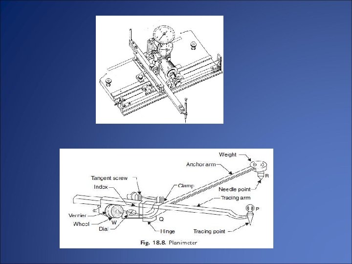
The various component parts of a polar planimeter is as follows: • Tracing arrow and Tracing point • Anchor arm • Anchor point • Rotating wheel • Graduated drum • Disc • Magnifier
Ø construction: It is consists of two arms hinged at a point known as the pivot point. One of the two arm is anchor arm , whose length is generally fixed. Anchor arm has got anchor point which is fixed either inside the plan or outside the plan depending upon tracing arm reach. . Other arm is called tracing arm having tracing point at its end. The length of the tracing arm is varied by means of a fixed screw which is attached with a slow motion screw.
Ø procedure : To find the area of the plan , the anchor point is either placed outside or inside the area depending upon whether the area is small or big. A point is then marked on the boundary of area and the tracing point is kept over it. The initial reading of the wheel is then taken. Then the tracing point is moved along the boundary till it comes to the original point. Then the final reading is noted.
(continue) Where F=final reading I=initial reading M= A multiplying constant. It is equal to area per revolution of the roller. N= The number of times the zero marks of dial passed the fixed index mark. C=instrument constant
Example : An area was measured using a planimeter with anchor point inside the figure. The initial and final readings were 4. 129 and 6. 387. The zero mark on disc passed the fixed index mark once in clockwise direction. If the value of M= 100 Sq. cm and constant of the instrument =24. 686. calculate the area of the figure. Solution: Final Initial M N Constant Here, I=4. 129 reading F=6. 387 4. 129 100 sq. cm 24. 686 M=100
(Continue) C= 24. 686
Zero circle It is also known as circle of correction. It is defined as the circle round the circumferences of which if the tracing point is moved , no rotation of the wheel will take place , but the wheel will slide on the paper without changing the reading. The anchor point is the centre of the zero circle and the line joining the anchor point is its radius. The area of zero circle may be determined by following methods
(continue) Ø By using formula: (a)Area of zero circle= M C Where M= multiplier C = the constant (b)Area of zero circle= Where L=the length of tracing arm L 1=the distance between the hinge and the wheel R=the length of anchor arm
Example : Find the area of zero circle from the following taken using planimeter having M=100 Sq. cm observations: Position of anchor point Initial reading Final reading Outside the figure 8. 596 4. 149 Inside the figure 3. 944 6. 534
(continue) Solution: Here , M=100 , I=8. 596 , F = 4. 149 , C=0 When the anchor point is inside, I=3. 944 , F=6. 534 , N=-2
(Continue)
q. Reference : • R. B. Khasiya Mahajan publication • R. Subramanian Oxford university press • R. P. Rethliya Atul prakashan