
Plan for test station Marta Bajko For the
Plan for test station Marta Bajko For the Technical Review of FRe. SCa 2 June 2015 Saclay Paris
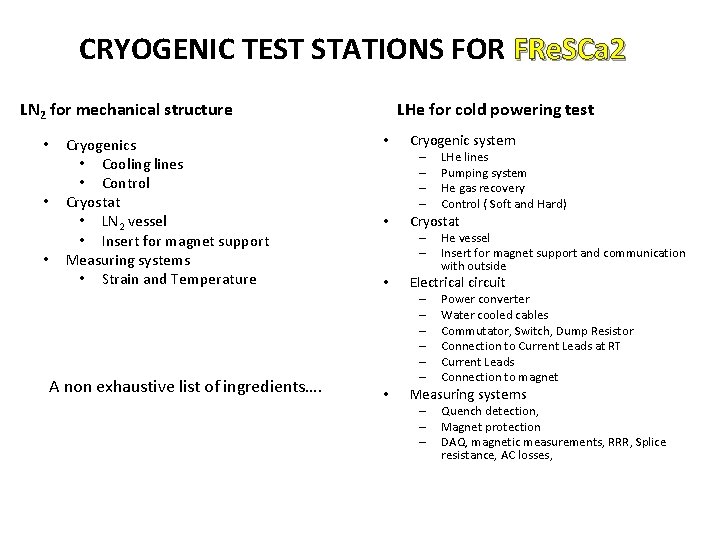
CRYOGENIC TEST STATIONS FOR FRe. SCa 2 LN 2 for mechanical structure • • • Cryogenics • Cooling lines • Control Cryostat • LN 2 vessel • Insert for magnet support Measuring systems • Strain and Temperature A non exhaustive list of ingredients…. LHe for cold powering test • Cryogenic system – – • Cryostat – – • He vessel Insert for magnet support and communication with outside Electrical circuit – – – • LHe lines Pumping system He gas recovery Control ( Soft and Hard) Power converter Water cooled cables Commutator, Switch, Dump Resistor Connection to Current Leads at RT Current Leads Connection to magnet Measuring systems – – – Quench detection, Magnet protection DAQ, magnetic measurements, RRR, Splice resistance, AC losses,
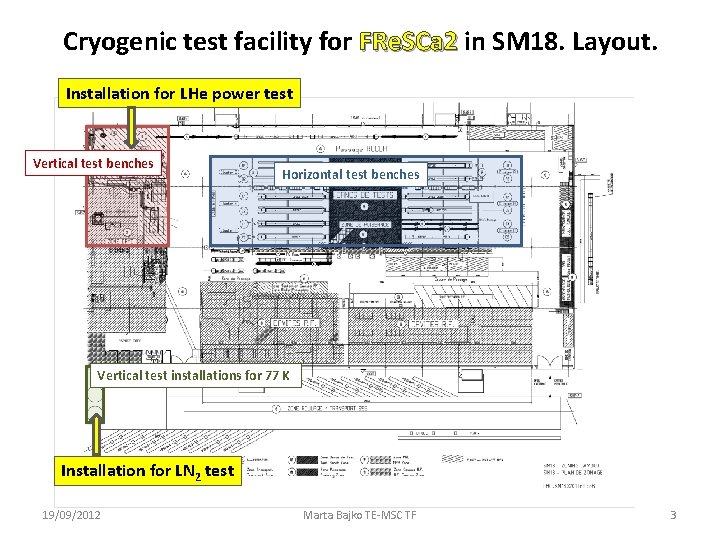
Cryogenic test facility for FRe. SCa 2 in SM 18. Layout. Installation for LHe power test Vertical test benches Horizontal test benches Vertical test installations for 77 K Installation for LN 2 test 19/09/2012 Marta Bajko TE-MSC TF 3
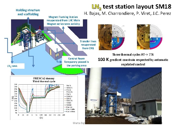
Holding structure and scaffolding LN 2 test station layout SM 18 Magnet Flushing Station recuperated from LHC Main Magnet series tests activity H. Bajas, M. Charrondiere, P. Viret, J. C. Perez Transfer lines recuperated from CRG Three thermal cycles RT 77 K LN 2 tank Cryostat borrowed from RF Control Room Temporary placed in the parking area 100 K gradient constrain respected by automatic Marta Bajko TE-MSC TF regulated control 4
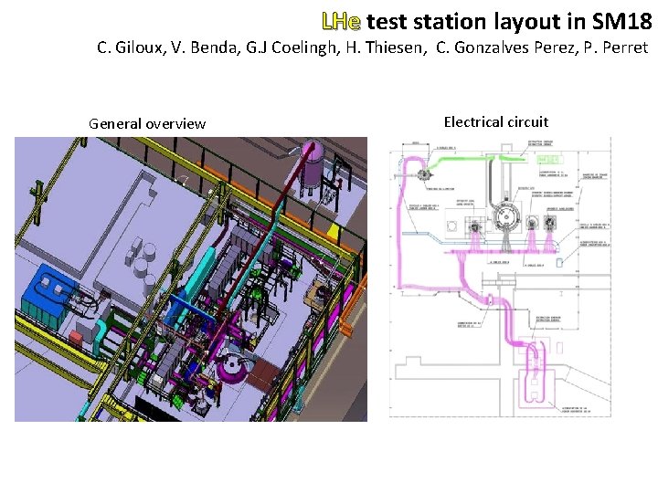
LHe test station layout in SM 18 C. Giloux, V. Benda, G. J Coelingh, H. Thiesen, C. Gonzalves Perez, P. Perret General overview Electrical circuit
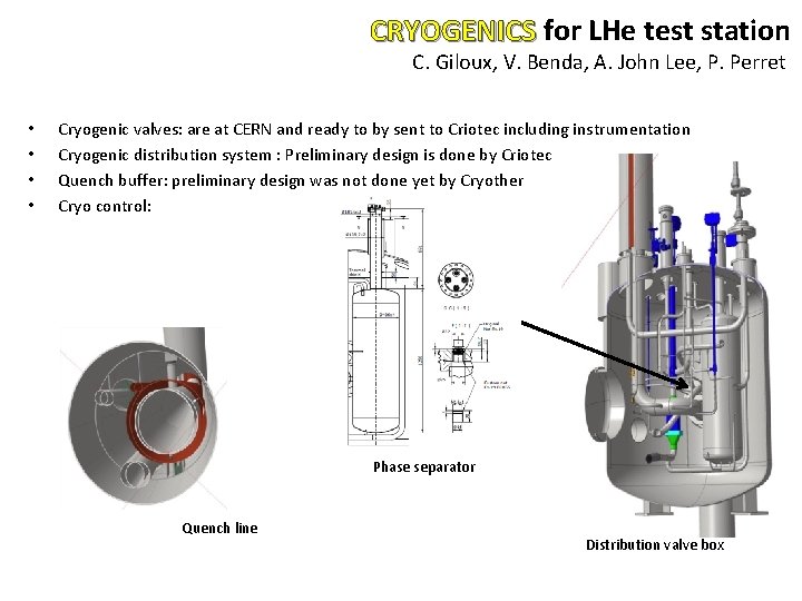
CRYOGENICS for LHe test station C. Giloux, V. Benda, A. John Lee, P. Perret • • Cryogenic valves: are at CERN and ready to by sent to Criotec including instrumentation Cryogenic distribution system : Preliminary design is done by Criotec Quench buffer: preliminary design was not done yet by Cryother Cryo control: Phase separator Quench line Distribution valve box
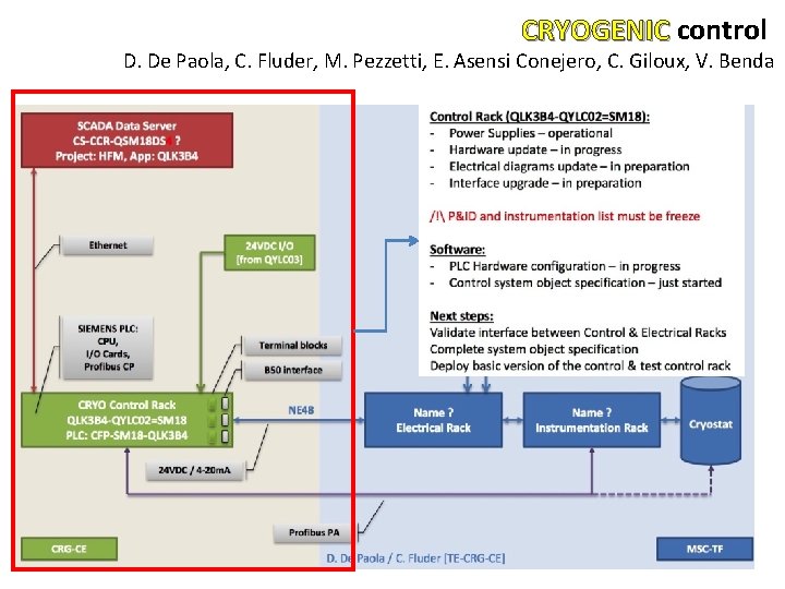
CRYOGENIC control D. De Paola, C. Fluder, M. Pezzetti, E. Asensi Conejero, C. Giloux, V. Benda
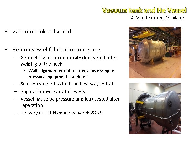
Vacuum tank and He Vessel A. Vande Craen, V. Maire • Vacuum tank delivered • Helium vessel fabrication on-going – Geometrical non-conformity discovered after welding of the neck • Wall alignment out of tolerance according to pressure equipment standards – Solution studied to find the best way to fix it – Reparation will start this week – Vessel has to be pressure and leak tested after reparation – Delivery at CERN expected week 28 -29
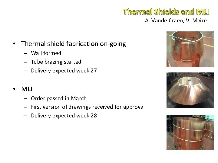
Thermal Shields and MLI A. Vande Craen, V. Maire • Thermal shield fabrication on-going – Wall formed – Tube brazing started – Delivery expected week 27 • MLI – Order passed in March – First version of drawings received for approval – Delivery expected week 28
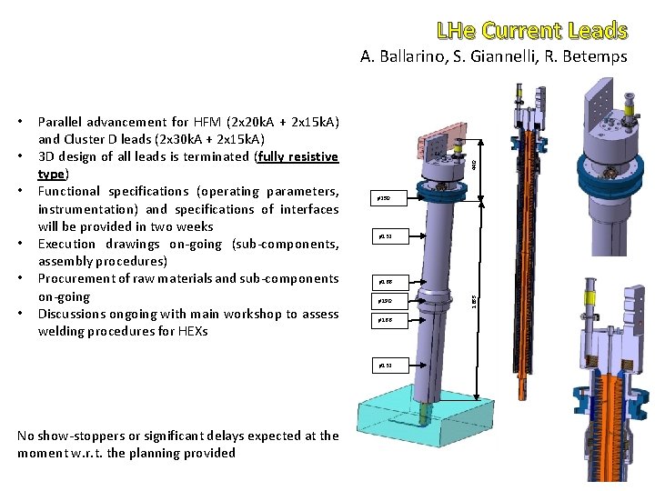
LHe Current Leads • • • Parallel advancement for HFM (2 x 20 k. A + 2 x 15 k. A) and Cluster D leads (2 x 30 k. A + 2 x 15 k. A) 3 D design of all leads is terminated (fully resistive type) Functional specifications (operating parameters, instrumentation) and specifications of interfaces will be provided in two weeks Execution drawings on-going (sub-components, assembly procedures) Procurement of raw materials and sub-components on-going Discussions ongoing with main workshop to assess welding procedures for HEXs ø 250 ø 132 ø 166 ø 190 ø 166 ø 132 No show-stoppers or significant delays expected at the moment w. r. t. the planning provided 1655 • 440 A. Ballarino, S. Giannelli, R. Betemps
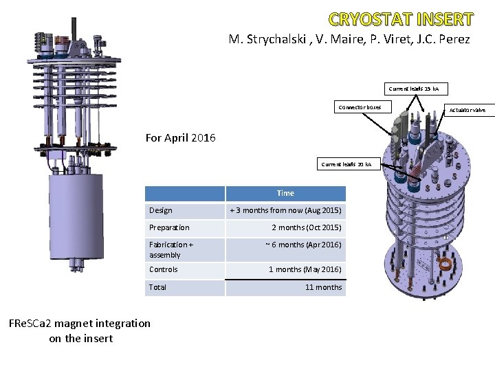
CRYOSTAT INSERT M. Strychalski , V. Maire, P. Viret, J. C. Perez Current leads 15 k. A Connector boxes For April 2016 Current leads 20 k. A Time Design Preparation Fabrication + assembly Controls Total FRe. SCa 2 magnet integration on the insert + 3 months from now (Aug 2015) 2 months (Oct 2015) ~ 6 months (Apr 2016) 1 months (May 2016) 11 months Actuator valve
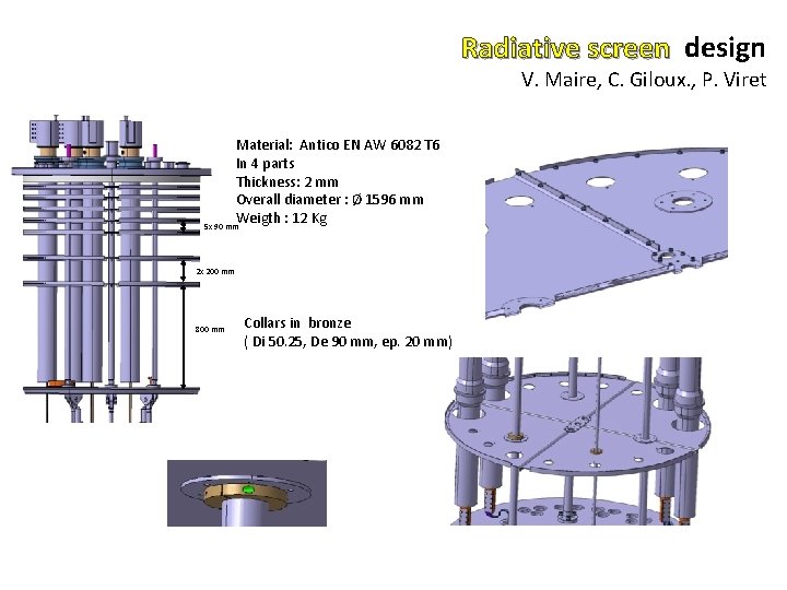
Radiative screen design V. Maire, C. Giloux. , P. Viret Material: Antico EN AW 6082 T 6 In 4 parts Thickness: 2 mm Overall diameter : Ø 1596 mm Weigth : 12 Kg 5 x 90 mm 2 x 200 mm 800 mm Collars in bronze ( Di 50. 25, De 90 mm, ep. 20 mm)
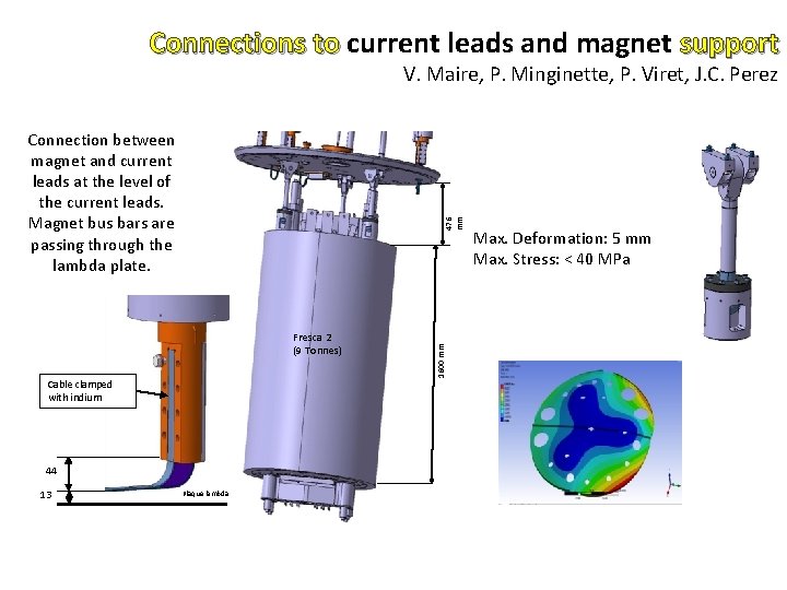
Connections to current leads and magnet support V. Maire, P. Minginette, P. Viret, J. C. Perez Fresca 2 (9 Tonnes) Cable clamped with indium 44 13 Plaque lambda 1600 mm 476 mm Connection between magnet and current leads at the level of the current leads. Magnet bus bars are passing through the lambda plate. Max. Deformation: 5 mm Max. Stress: < 40 MPa
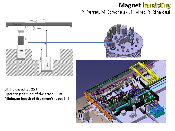
Magnet handeling P. Perret, M. Strychalski, P. Viret, R. Rinaldesi Lifting capacity : 25 t Operating altitude of the crane : 6 m Minimum length of the crane’s rope: 9. 3 m
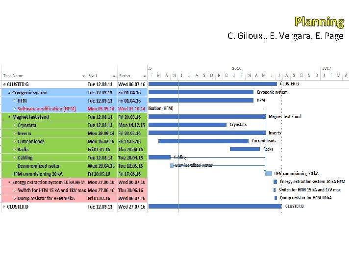
Planning C. Giloux. , E. Vergara, E. Page
- Slides: 15