PIPING MATERIALS Definition piping components mechanical elements suitable

PIPING MATERIALS

Definition: Ø piping components: mechanical elements suitable for joining or assembly into pressure tight fluidcontaining piping systems include

Piping components: Ø piping components includes: ü Pipe & tube ü Flange ü gaskets, bolting ü valves ü Fittings (e. g. elbows, reducers, branch, connections, etc. ) ü Special items such as expansion joints…

Piping components: pipe & tube classification ² Tube: – Specify by two of • Outside diameter • Wall thickness: ² Pipe : – Specify by two of • NPS (Nominal Pipe Size) • Wall Thickness (Schedule) Tube : Heat conduction Pipe : Fluid transferring

Classifications Ferrous Material Non Metallic Max. Temp. Services Material Spec. Carbon Steel 427 °C (800°F) L&I Temp. L&I Press. A 53, AI 06 Low & Intermediate Alloy Steel 648 °C (1200°F) High Temp. I&H Press. A 335, A 691 Stainless Steels (High Alloy Steel) 648 °C (1200°F) Corrosive Media, Purity Maintenance A 213, A 312 Stainless Steels for High Temperature 815°C (1500°F ') High Temp (above 1200 OF) A 312 Cast Iron 204°C (400°F) Low Temp & Press. , Civil A 48, A 395 Nickel & High Nickel Alloys 343 °C (650°F) L&I Temp, Corrosive Media B 161, B 167 Copper & Copper Alloys 427°C (800°F) Sea Water for Low Temp & Press. B 466 etc. Aluminum & Aluminum Alloys 204 °C (400°F) Light Weight B 21 O etc. Titanium & Titanium Alloys 315°C (600°F) Light Weight 8337 etc Thermoplastic 426°C (800°F) Low Temp & Press D 1527 etc. Laminated Reinforced Thermosetting Resin 149°C (300°F) Low Temp & Press C 582 etc. Filament-Wound Thermosetting Resin (GRP) 110°C (230°F) Low Temp & Press D 2996 etc Concrete 93°C (200°F) U/G Piping for Low Temp & Press AWWA C 300 etc. Rubber 121°C (250°F) Low Temp & Press, Corrosive Media NR, NBR etc Glass 230 °C (450°F) High Purity Maintenance C 599 etc.

Material Specification List

Piping components: pipe & tube classification Ø Pipe: ─ NPS: ½”, ¾”, 1 ½”, 2”, 3”, 4”, 6”, 8”, 10”, 12”, 14”, 16”, 18”, 20”, 24”, 28”, 30”, 32”, 36”, 40”, 44”, 48” 52”, 56”, 60” • NPS < 12, OD > NPS • NPS ≥ 14, OD = NPS ─ NPS 1 ¼”, 2 ½”, 3 ½”, 5” not used ─ Pipe is supplied in ─ Random length (17 to 25 ft) ─ Double random length (38 to 48 ft) ─ Pipe end: ─ BE (bevel end) ─ PE (plain end) ─ TE or SC

Piping components: pipe & tube classification Required Wall Thickness for Internal Pressure of Straight Pipe IN ASME B 31. 3 – – t = Required thickness for internal pressure, mm D= Nominal outside diameter of pipe, mm P = Internal design pressure, psig S = Allowable stress in tension from appendix A table A-1, psi – E = Longitudinal-joint quality factor from appendix A, table A-1 B – Y = stress-temperature compensating – tm = Total minimum required wall thickness, mm

Piping components: pipe & tube classification Ø Pipe classification: ─ Iron pipe size (approximate internal dia. ) ─ Manufacturers’ weight: NPS + • STD • XS • XXS ─ Schedule number: NPS + • 5, 5 s, 10 s, 20 s, 30, 40 s, 60, 80 s, 100, 120, 140, 160 Show • SCH ≈ 1000 P/S • NPS ≤ 10, SCH 40 = STD • NPS ≤ 8, SCH 80 = XS • Light wall = light gage = 5, 5 s, 10 s

Piping components: Pipe & tube manufacturing Ø Seamless Ø Welded: ─ Longitudinal seam • Single seam • Double seam (NPS ≥ 36”) ─ Helical (spiral) seam ─ NPS ≥ 4 ½” • 0. 8 OD ≤ Skelp width ≤ 3. 0 OD • Submerged arc welding

Piping components: Pipe & tube manufacturing : other pipe

Piping components: pipe & tube Jointing Ø Method of joining pipe: ─ ─ ─ Butt weld Socket weld Threaded Quick coupling Flange Special item
 ² ASME B 16. 9 ² Used in most piping")
Piping components: Fitting (butt-weld) ² ASME B 16. 9 ² Used in most piping systems NPS ≥ 2” ² Use generally not restricted ² Difficult in small sizes, especially for thin wall
 ² Size frequently limited to NPS≤ 1 ½” (ASME B")
Piping components: Fitting (socket) ² Size frequently limited to NPS≤ 1 ½” (ASME B 16. 11) ² Not used in “severe cyclic conditions” and in services where corrosion is accelerated in crevices ² No weld metal can enter bore, easier alignment on small line than butt-weld ² Tack is unnecessary ² Have not any leakage
 ² ─ ─ Common materials – Gray iron")
Piping components: Fitting (threaded = screwed) ² ─ ─ Common materials – Gray iron (ASME B 16. 4) – Malleable iron (ASME B 16. 3) – Steel (ASME B 16. 11) Non-toxic, non-flammable, Generally not used where leaks cannot be tolerated NPS ≤ 1 ½” , pressure rating < 600, temperature < 625

Piping components: Flange ² Flange used for – Mate to equipment, vessels, valve, … – When need periodic cleaning – Flanges are normally used for pipe sizes above NPS 1½”.

Piping components: Flange ² Flange Rating Class: – pressure/temperature combinations – Seven classes (150, 300, 400, 600, 900, 1, 500, 2, 500) – Flange strength increases with class number – The material specifications are grouped within Material Group Numbers.

Piping components: Flange ² Pressure - Temperature Ratings ² Material and design temperature combinations that do not have a pressure indicated are not acceptable.

Piping components: Flange ² Flange Rating Class

Piping components: Flange ² Flange Rating Class

Piping components: Flange Ø Type of flange end: – – – Weld Neck Flanges Socket-Welded Flanges Threaded Flanges Slip-On Flanges Lapped Flanges

Piping components: Flange ü Flange Facing Types ü Flat Faced ü Raised Face ü Ring Joint

Piping components: Flange ² Welding neck flange – Regular – Long (used for vessel & equipment nozzle, rarely for pipe ² Suitable where – Extreme temperature – Shear – Impact and vibration Stress apply

Piping components: Flange ² Socket welding flange

Piping components: Flange ² Threaded flange

Piping components: Flange ² Slip-on flange – Internal welds is slightly more subject to corrosion than the butt-weld (0 – 1/16”) – Poor resistance to shock and vibration – Cheaper to buy, costlier to assemble – Strength under internal pressure 1/3 of corresponding welding neck flange – Easier to align than the welding neck flange

Piping components: Flange ² Reducing flange – Specify by size of smaller pipe and outside diameter of flange to be mate • Ex/ RED FLG 4” × 11” – Should not be used if abrupt transition would create undesirable turbulence as at pump

Piping components: Flange ² Expander flange – Reducer + welding neck flange – Increase pipe size to first or second large size
 flange – If stub and flange")
Piping components: Flange ² Lap joint (van stone) flange – If stub and flange are of the same material they will be more expensive than a welding neck flange – Economical for different material of stub and flange
 ² Spectacle blind")
Piping components: Fitting (special item) ² Spectacle blind

Piping components: Flange ² Blind flange

Piping components: Gasket / Bolt & Not ² Gasket: – – Resilient material Inserted between flanges Compressed by bolts to create seal Commonly used types • Sheet • Spiral wound • Solid metal ring • Insulation gasket
 ² Sheet")
Piping components: Fitting (gasket) ² Sheet
 ² Sheet")
Piping components: Fitting (gasket) ² Sheet
 ² Spiral wound")
Piping components: Fitting (gasket) ² Spiral wound
 ² Spiral wound")
Piping components: Fitting (gasket) ² Spiral wound
 ² Spiral wound")
Piping components: Fitting (gasket) ² Spiral wound
 ² Solid metal ring")
Piping components: Fitting (gasket) ² Solid metal ring
 ² Insulation gasket")
Piping components: Fitting (gasket) ² Insulation gasket
 ² Bolt type: – Stud bolt • Easily remove if")
Piping components: Fitting (bolt) ² Bolt type: – Stud bolt • Easily remove if corroded • Material can be readily made – Machine bolt ² Has to be strong enough to seat the gasket
 ² Tightening arrangement")
Piping components: Fitting (bolt) ² Tightening arrangement

Piping components: valve Valves ² Valve are use for – Controlling process and utility service – Isolating equipment or instrument for maintenances – Discharge gas, vapor or liquid – Draining piping and equipment on shutdown – Emergency shutdown

Piping components: valve ² Classify valves according to functions: – – – Block flow (On / Off) Regulating (Throttle flow) Checking (Prevent flow reversal) Switching Discharging (pressure relive valve) ² Classify valves according to operating device: – – Manual Hydraulic Motor (electric and air operated) Solenoid
")
Piping components: valve (result)

Piping components: valve ² Type of valves: – – – – – Ball valves Gate valves Globe valves Check Valves Plug valve Butterfly valves Pinch valve Needle valves Relief Valve
")
Piping components: valve (ball valve)
 ² Used for isolation (quick on / off) ²")
Piping components: valve (ball valve) ² Used for isolation (quick on / off) ² Soft-sealed ball valves are not normally used for throttling service because the soft-seats are subject to erosion or distortion/displacement caused by fluid flow when the valve is in the partially open position. ² ADV: Low pressure drop, fast operating, bubble-tight shut off, can be throttled Check Valves ² DISADV: Expensive, heavy, poor throttling
")
Piping components: valve (gate valve)
 ² About 75% of all valves in process plants")
Piping components: valve (gate valve) ² About 75% of all valves in process plants ² an optimum engineering and economic choice for on or off service. (cutout or isolation valves) ² ADV: small pressure drop across valve ² DISADV: poor throttling characteristics
")
Piping components: valve (globe valve)
 ² Most economic for throttling flow and used for")
Piping components: valve (globe valve) ² Most economic for throttling flow and used for flow control ² Can be hand-controlled ² Provides “tight” shutoff ² Not suitable for scraping or rodding ² Too costly for on/off block operations ² ADV: excellent throttling characteristics ² DISADV: large pressure drop across the valve due to the flow restriction (thus more pumping power is required to move the fluid through the system. )
")
Piping components: valve (globe valve)

Gate Vlv disk Globe vlv disk/seat
")
Piping components: (check valve / swing check valve)
 ² Simple design ² Allows flow")
Piping components: (check valve / swing check valve) ² Simple design ² Allows flow in one direction ² Can not be used as an isolation valve
")
Piping components: (check valve / ball check valve)
 ² Their low cost usually makes")
Piping components: (check valve / ball check valve) ² Their low cost usually makes them the first choice valves sized NPS 2 and smaller (available in sizes NPS ½ through 2) ² Used when pressure drop is not a concern. ² The basic types are the straight-through- and globe-type (90 change in direction)
")
Piping components: (check valve)
 ² are available in sizes from")
Piping components: (check valve / lift check valve) ² are available in sizes from NPS ½ through 2 plants. ² They are most commonly used in the higher ASME B 16. 5 ratings (Class 300 and greater) where tighter shutoff is required. ² Valves of this type should only be used in clean services.
 Wafer Check Valve")
Piping components: (check valve) Wafer Check Valve
 ² Valves of this type are")
Piping components: (check valve / wafer check valve) ² Valves of this type are placed between pipe flanges and held in place by the compressive force between the flanges and transmitted through the gaskets.

A r c V a l v e (A u to m a ti c R e c i r c u l a ti o n V a l v e ) Tilting Check Valve
")
Piping components: (check valve)
 Plug Valve")
Piping components: valve (plug valve) Plug Valve
 Butterfly Valve")
Piping components: valve (butterfly valve) Butterfly Valve
 ² used as cutout/isolation valves ² ADV: quick-acting low")
Piping components: valve (butterfly valve) ² used as cutout/isolation valves ² ADV: quick-acting low pressure drop across the valve, has adequate throttling characteristics ² DISADV: only used for low press/low temp systems due to force involved in valve operation
 Pinch Valve")
Piping components: valve (pinch valve) Pinch Valve
 Needle Valve")
Piping components: valve (needle valve) Needle Valve

Piping components: valve Relief Valve


Piping components: Fitting ² Fitting produce change in geometry and include: – Change in direction of piping – Alter pipe diameter – Terminate pipe – Bring pipes together (made branch from main pipe run)
 ² Elbow (90, 45) – Long reduce • Curvature =")
Piping components: Fitting (butt-weld) ² Elbow (90, 45) – Long reduce • Curvature = 1 ½ NPS • Long tangent: straight extension at one end – Short reduce • curvature = NPS ² Reducing elbow: – 90 – curvature = 1 ½ NPS larger end
 Buckling Tolerance (PFI ES-24)")
Bend Ovality (limit 8% internal press) Buckling Tolerance (PFI ES-24)
 ² Return: – Curvature = 1 ½ NPS – Uses")
Piping components: Fitting (butt-weld) ² Return: – Curvature = 1 ½ NPS – Uses in: • Vent on tanks ² Bend: – Curvature = 4 - 6 NPS – Made from seamless and ERW straight pipe – Two methods used to making bend • Hot • Cold
 ² Miter – – 2 piece (pressure drop ≈ 4")
Piping components: Fitting (butt-weld) ² Miter – – 2 piece (pressure drop ≈ 4 -6 LR elbow) 3 piece (pressure drop ≈ 2 LR elbow) Low pressure line, NPS > 10” & pressure drop not important 90
 ² Reducer – Eccentric • Suction & discharge of pump")
Piping components: Fitting (butt-weld) ² Reducer – Eccentric • Suction & discharge of pump • support – concentric
 ² Sewage : – connect butt-welded piping to smaller socket-weld")
Piping components: Fitting (butt-weld) ² Sewage : – connect butt-welded piping to smaller socket-weld or screwed – Abrupt change of line size in butt-weld Type: • Eccentric • Concentric • Venturi: Allows smoother flow
 ² Tee – Straight (branch to the same size as")
Piping components: Fitting (butt-weld) ² Tee – Straight (branch to the same size as the run) – Reducing • Branch smaller than the run – Bullhead tee have branch larger than run & seldom used and made to special order
 ² Cross – Straight (branch to the same size as")
Piping components: Fitting (butt-weld) ² Cross – Straight (branch to the same size as the run) – Reducing (rarely used)
 ² Lateral (manufacture in factory) – Run inlet × run")
Piping components: Fitting (butt-weld) ² Lateral (manufacture in factory) – Run inlet × run outlet × branch × angle respect to outlet (6 × 4 × 45) ² Shape nipple (use template) – Manufacture at shop – Rarely use – 90, 45 45
 ² Stub-in – – Welded directly in the side of")
Piping components: Fitting (butt-weld) ² Stub-in – – Welded directly in the side of the main pipe run Least expensive NPS ≥ 2” Cab be reinforced
 ² Weldolet – – Make a closer manifold that Tee")
Piping components: Fitting (butt-weld) ² Weldolet – – Make a closer manifold that Tee Full size Reducing Flat • Are available for connecting to pipe caps and pressure vessel
 ² Elbolet: reducing tangent branch on elbow ² Latrolet :")
Piping components: Fitting (butt-weld) ² Elbolet: reducing tangent branch on elbow ² Latrolet : reducing, 45 ² Sweepolet – Good flow pattern and optimum stress distribution – 90 reducing from the main pipe
 ² Closure – Cap – Flat closure")
Piping components: Fitting (butt-weld) ² Closure – Cap – Flat closure
 ² Elbow (90, 45)")
Piping components: Fitting (socket) ² Elbow (90, 45)
 ² Return:")
Piping components: Fitting (socket) ² Return:
 ² Reducer insert")
Piping components: Fitting (socket) ² Reducer insert
 ² Sewage : – Abrupt change of line size in")
Piping components: Fitting (socket) ² Sewage : – Abrupt change of line size in butt-weld
 ² Full coupling ² Half coupling")
Piping components: Fitting (socket) ² Full coupling ² Half coupling
 ² Union")
Piping components: Fitting (socket) ² Union
 ² Tee")
Piping components: Fitting (socket) ² Tee
 ² Cross")
Piping components: Fitting (socket) ² Cross
 ² Lateral")
Piping components: Fitting (socket) ² Lateral
 ² Sockolet")
Piping components: Fitting (socket) ² Sockolet
 ² Socket welding Elbolet ² Socket welding latrolet ² Nippolet")
Piping components: Fitting (socket) ² Socket welding Elbolet ² Socket welding latrolet ² Nippolet
 ² Cap")
Piping components: Fitting (socket) ² Cap
 ² Elbow (90, 45) ² Reducing elbow")
Piping components: Fitting (thread) ² Elbow (90, 45) ² Reducing elbow
 ² Reducer insert")
Piping components: Fitting (thread) ² Reducer insert
 ² Sewage nipple")
Piping components: Fitting (thread) ² Sewage nipple
 ² Full coupling ² Half coupling")
Piping components: Fitting (thread) ² Full coupling ² Half coupling
 ² Tee")
Piping components: Fitting (thread) ² Tee
 ² Nipple")
Piping components: Fitting (thread) ² Nipple
 ² cross")
Piping components: Fitting (thread) ² cross
 ² lateral")
Piping components: Fitting (thread) ² lateral
 ² Union")
Piping components: Fitting (thread) ² Union
 ² Hexagon bushing")
Piping components: Fitting (thread) ² Hexagon bushing
 ² Threadolet")
Piping components: Fitting (thread) ² Threadolet
 ² Threaded elbolet ² Threaded latrolet ² Threaded nippolet")
Piping components: Fitting (thread) ² Threaded elbolet ² Threaded latrolet ² Threaded nippolet
 ² Closure – Cap – plug")
Piping components: Fitting (thread) ² Closure – Cap – plug
 ² Expansion joint (Bellows)")
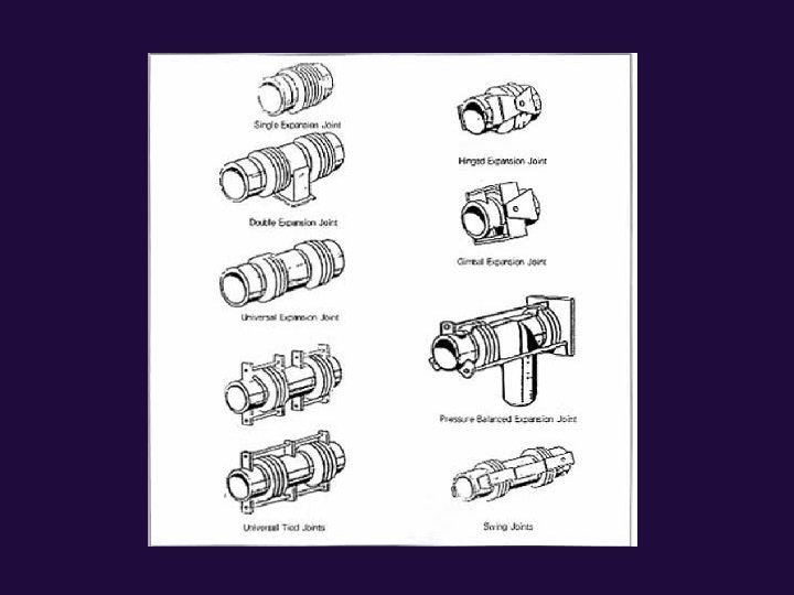
Piping components: Fitting (special item) ² Expansion joint (Bellows)
 ² Expansion joint")
Piping components: Fitting (special item) ² Expansion joint
 ² strainer")
Piping components: Fitting (special item) ² strainer
 Basket type strainer Filter Wye type")
Cone type Strainer and Filter: Strainer (start up) Basket type strainer Filter Wye type strainer
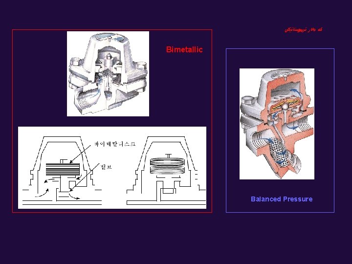
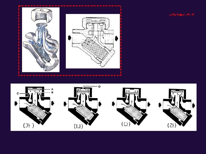
 ﺗﻠﻪ ﺑﺨﺎﺭ ﻣکﺎﻧیکی Ball Float Inverted Bucket")
(Steam Trap) ﺗﻠﻪ ﺑﺨﺎﺭ ﻣکﺎﻧیکی Ball Float Inverted Bucket
")
Piping components: Fitting (piping specification)
")
Piping components: Fitting (gasket)
")
Piping components: Fitting (branch connection chart)
- Slides: 120