PIPELINED PROCESSORS Chapter No 5 Pipeline Evolution in


- Slides: 43
PIPELINED PROCESSORS Chapter No. 5
Pipeline Evolution in Processors z First appeared in at the end of 1960 s in the first supercomputers of that time such as IBM 360/91 (1967) and the CDC 7600 (1970). z In 1970 the use of pipelining at instruction level in mainframe B 7700.
Principle of Pipelining z A number of functional units are employed in sequence to perform a single computation. z Each functional unit represent a certain stage of computation. z Pipeline allows overlapped execution of instructions or temporal overlapping of processing. z It increases the overall processor’s throughput. z In pipelined operation each task is divided into a number of subtasks.
Principle of Pipelining z Each stage of pipeline is associated with each subtask which performs required operation. z For a basic pipeline same amount of time is available in each stage for performing a certain task. z All the pipeline stages operate like assembly line, that is , receiving input typically from previous stage and delivering their output to the next stage. z The basic pipeline operates clocked (synchronously), that is each stage accepts a new input at the start of the clock cycle.
Principle of Pipelining
Pipelined Operation
Pipelined Operation
Pipelined and Unpipelined Processing
Processor Pipelines in Reality z A real pipeline may include a few extensions to basic pipeline. z Pipelined execution is also often performed using half-cycles. and in certain cases, one or more pipeline stages may have to be recycled to accomplish a given task. z These additional cycles may be required to perform certain arithmetic operations
Logical Layout of Pentium Pipeline
Logical Layout of Power. PC 604 Pipeline
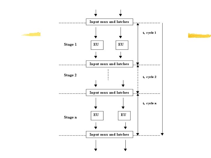
General Structure of Pipelines z Pipeline consists of a number of stages, one for each subtask. The stages are decoupled from each other by registers, called latches. z As each clock cycle ends, the latches gates in their inputs and forward them into the associated stage where the required operation is performed. z In reality, each stage is often implemented by a number of different FUs/Eus in performing the required operations. z The latches are extended with multiplexers that selects and transfer data from the outputs of preceding Eus to input the subsequent execution units.
General Structure of Pipelines
Pipeline Performance Measures z Non-pipelined processor ycharacteristic is instruction cycle time and execution time z Pipelined processor yno importance of execution time ythree different measures in pipelined processors: cycle time, latency and repetition rate z Cycle time yspecifies the time available for each stage to accomplish the required operations
Pipeline Performance Measures ydetermined by worst-case processing time of the longest stage z latency yspecifies the amount of time that the result of a particular instruction takes to become available in the pipeline for a subsequent dependent instruction yused in context of processing subsequent RAW dependent instruction z Two kinds of latencies define-use dependency and load-use dependency (corresponds to two types of RAW dependencies)
Pipeline Performance Measures ydefine use latency xmul r 1, r 2, r 3 xadd r 5, r 1, r 4 ydefine-use delay xthe time a subsequent RAW-dependent instruction has to be stalled in a pipeline yload-use latency r 1, x add r 5, r 1, r 2 y. Load-use delay xinterpreted same as define-use delay
Pipeline Performance Measures z Repetition rate yalso known as throughput yspecifies the shortest possible time interval between the subsequent instructions in pipeline the repetition rate of a basic pipeline is one cycle yrepetition rate is the performance potential of a pipeline y. Performance potential of a pipeline with no define-use delay or load-use delay exist between instructions can be calculated as: P= 1/R*tc
Pipeline Performance Measures where: R: is the repetition rate of the pipeline in cycles tc: is the cycle time of the pipeline
Application Scenarios of Pipelines
Design space of pipelines Key aspects of the design space of pipelines
Basic Pipeline Layout
Basic Pipeline Layout z The number of pipeline stages ywhen more pipeline stages are used, more parallel execution and thus a higher performance can be expected ydisadvantage: more number of stages results in frequent data and control dependencies which decreases performance z specification of the subtasks to be performed in each stage y the specification of the subtasks at a number of levels of increasing details
Number of Pipeline Stages
Number of Pipeline Stages
Basic Pipeline Layout z Layout of the stage sequence yconcerns how the pipeline stages are used z use of bypassing yintended to reduce or eliminate pipeline stalls due to RAW dependencies y. Problem: Unless special arrangements are made, the results of the operation instruction is written into the register file, or into the memory, and then it is fetched from there as a source operand y. Solution: the result of the EU is immediately forwarded to its input for use in the next pipeline cycle
Layout of the Stage Sequence
Bypassing
Basic Pipeline Layout y. Its implementation requires an additional data bus forwarding the results of the execution stage to its input and an appropriate extension of the associated multiplexers and latches z timing of the pipeline operations yself-timed(asynchronous) yclocked (synchronous)
Timing of Pipeline Operations
Dependency Resolution Method of dependency resolution Static resolution performed by the compiler Combined resolution performed partly by the compiler & partly by the hardware Dynamic resolution performed by extra hardware Trend
Overview of Pipelined Instructions
Logical Layout z It specifies the tasks to be accomplished, this includes: ythe declaration of pipeline to be implemented xusually separate pipelines for the processing of FX and logical data, called FX pipeline, for FP data, the FP pipeline, for loads and stores, L/S pipeline, and for branches , the B pipeline x. DEC a 21164 provides two types of FX integer pipelines ydetailed specification of subtasks to be performed and their execution sequence for each pipeline xdetailed description of the subtasks to be performed in each stage
Power PC 601 Example
Detailed Description of FX Pipeline
Implementation of Instruction Pipeline
Layout of the Physical Pipelines
Layout of the Physical Pipelines z Multifunction y. Only one published design of multifunction pipeline is available and that is MIPS R 4200 which implements all the FX, FP, L/S and B instructions y. Classical approach/ Master pipeline approach is implemented in IBM 801, MIPS-X, MIPS Rseries (up to the R 6000), i 486, & Pentium z Dedicated pipelines ydedicated pipelines are implemented in power PC 603, Power PC 604, DEC a etc
Multiplicity of Pipelines z multiplicity refers to the concept that whether to use a single instance of physical pipeline or multiple instances of physical pipelines. z Two aspects should be considered while considering pipeline multiplicity yfrequency of instructions yout-of-order execution of instructions due to multiple pipelines
Multiplicity of Pipelines
Preserving Sequential Consistency
Implementation Pipelined Instruction Processing
Implementation Pipelined Instruction Processing