Pion capture and transport system for PRISM M


![Geometry of Pion Capture System 100 magnetic field [Tesla] 300 900 600 To transport](https://slidetodoc.com/presentation_image_h2/4b8a22031eeb1028dd2bc89b8ebfba76/image-7.jpg "Geometry of Pion Capture System 100 magnetic field [Tesla] 300 900 600 To transport")


- Slides: 15
Pion capture and transport system for PRISM M. Yoshida Osaka Univ. 2005/8/28 Nu. FACT 06 at UCI
PRISM/PRIME project n n Phase Rotated Intense Slow Muon source Collect 68 Me. V/c m- PRIME detector proton beam pion production, capture and transport system Phase rotator
Concepts of pion capture/transport system for PRISM n Capture low-energy pions produced in Graphite target with 6 T solenoid field ¡ Low-Z material n ¡ Collect backward pions from the target n n ¡ ¡ ¡ n Direction of emitted low energy pions is almost isotropic helps to reduce radiation heating on cold mass (avoid high energy hadrons) Tilt target by 10 deg. to implement proton beam pipe Energy deposit on superconducting coil of capture solenoid < 100 W Al-stabilized SC coil to reduce cold mass Transport pions+muons in long 2 T solenoid channel ¡ Bent solenoid channel n n n to avoid absorption in the target Target should be off-site from experimental area Reduce background by wiping out higher energy particles The first trial of conceptual design has been done.
Heat load estimation MARS Simulation n n ¡ ¡ ¡ n ¡ 5 cm Graphite (1. 7 g/cm 3) radius=2 cm Tungsten shield Magnetic field ¡ ¡ n 40 Ge. V size s=1. 0 cm 1014 protons/sec Target ¡ n 140 cm MARS 15(04) Primary beam uniform 6 Tesla Solenoid inner R=15 cm Coil ¡ Al-stabilized superconducting Coil n n 71%Al + 11%Nb. Ti + 14%Cu + 4%G 10 -tape density 3. 1 g/cm 3 15 cm protons
Heat load on coil 80 cm-long graphite target Coil: 89 W Shield: 41 k. W Choose lthickness of shield = 30 cm lthickness of coil = 12 cm 17 A/mm 2 ltarget length = 60 cm
Spatial distribution of deposit energy 270 0 180 90
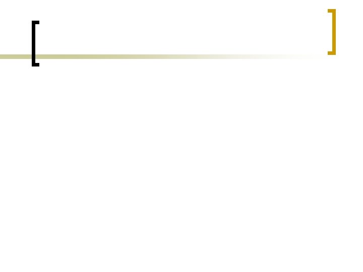
Geometry of Pion Capture System 100 magnetic field [Tesla] 300 900 600 To transport solenoid 500 3600 1400
p-, m- distributions @3 m n 0. 058 p-+m-/POT @3 -meter downstream traget 10 cm 15 cm 20 cm 25 cm Pt Radius squared (cm 2) Total momentum (Ge. V/c)
Transport solenoid channel n n Transport pions and muons in 2 T solenoid Bent towards experimental area ¡ put radiation shield along proton beam line
Parameters of transport solenoid arc radius : 4000 mm bend angle : 90 deg. Bs : 2 T By : 0. 05 T coil inner raduis : 350 mm (inner wall : 50 mm) coil thickness : 50. 0 mm coil length : 629. 0 mm current : 36. 5 A/mm^2 step angle : 10 deg. 4 meters 10 deg. A. Sato
Transport loss in bent solenoid Before BS π -: 9056 μ -: 21009 total : 30065 -7% After BS π -: 2041 μ -: 26089 total : 28130 G 4 Beam. Line Simulation A. Sato
Summary n n Conceptual design of pion capture solenoid and transport bent solenoid has been performed for PRISM Heat load on coils of capture solenoid can be less than 100 W as 40 Ge. V proton beam injected, assuming 0. 6 MW beam power. Design works for the solenoid magnets are being started in collaboration with KEK To improve pion yield ¡ ¡ Reduce beam spot size on target Field gradient around the target n n acceptance would increase by mirroring forward pions To fit to FFAG acceptance (H: 40 p mm-rad, V: 6. 5 p mm-rad) ¡ optimize field profile in the capture system to reduce muon emittance. (keep higher field? )
Horizontal position/direction distribution at exit of transport solenoid Smooth curve bend in 3 steps
Capture Matching Bent Injection Point:s=7 m Post