PIN RETAINED RESTORATIONS Dr Rakesh Kumar Yadav INTRODUCTION


. �Access difficulties-In class V horizontal")


![MECHANICAL ASPECTS �A] STRESSING CAPABILITIES OF PINS �B] RETENTION OF PINS IN DENTIN �C]](https://slidetodoc.com/presentation_image/1c50e351efa68d2ced6d35227a6b4c2e/image-26.jpg "MECHANICAL ASPECTS �A] STRESSING CAPABILITIES OF PINS �B] RETENTION OF PINS IN DENTIN �C]")
![MECHANICAL ASPECTS [PINS AND TOOTH STRUCTURE] A] Stressing capabilities of pins � Type of](https://slidetodoc.com/presentation_image/1c50e351efa68d2ced6d35227a6b4c2e/image-27.jpg "MECHANICAL ASPECTS [PINS AND TOOTH STRUCTURE] A] Stressing capabilities of pins � Type of")


![B] RETENTION OF PINS IN DENTIN �Type of pin �Pin depth and dentinal engagement](https://slidetodoc.com/presentation_image/1c50e351efa68d2ced6d35227a6b4c2e/image-30.jpg "B] RETENTION OF PINS IN DENTIN �Type of pin �Pin depth and dentinal engagement")
![�Type of cement �Ratio of dentinal engagement : pin protrusion [ideal 2: 1] �Type](https://slidetodoc.com/presentation_image/1c50e351efa68d2ced6d35227a6b4c2e/image-31.jpg "�Type of cement �Ratio of dentinal engagement : pin protrusion [ideal 2: 1] �Type")
![C] MICROCRACKING AND CRAZING �Type of pin �Proximity of pin to DEJ �Induced stresses](https://slidetodoc.com/presentation_image/1c50e351efa68d2ced6d35227a6b4c2e/image-32.jpg "C] MICROCRACKING AND CRAZING �Type of pin �Proximity of pin to DEJ �Induced stresses")


- Slides: 59
PIN RETAINED RESTORATIONS Dr Rakesh Kumar Yadav
INTRODUCTION �Most of the teeth can be restored with amalgam and composite but if large crown portion lost due to caries or some other reasons, the remaining tooth structure is decrease and difficult to obtained resistance and retention form so prepare dentine lock and slot but when these retention features are insufficient to provide desired retention then pin supported restorations are used.
TRETMENT OF BADLY BROKEN TOOTH �First-Evaluate biologically and mechanically �Status of pulp and periodontium should be evaluated. �Involvement of pulp or not � Restorative design planning if pulp is not involve-pin, inlay, onlay �Pulp involvement- pulpotomy , pulpectomy, pin, full coverage�Tooth anterior or posterior
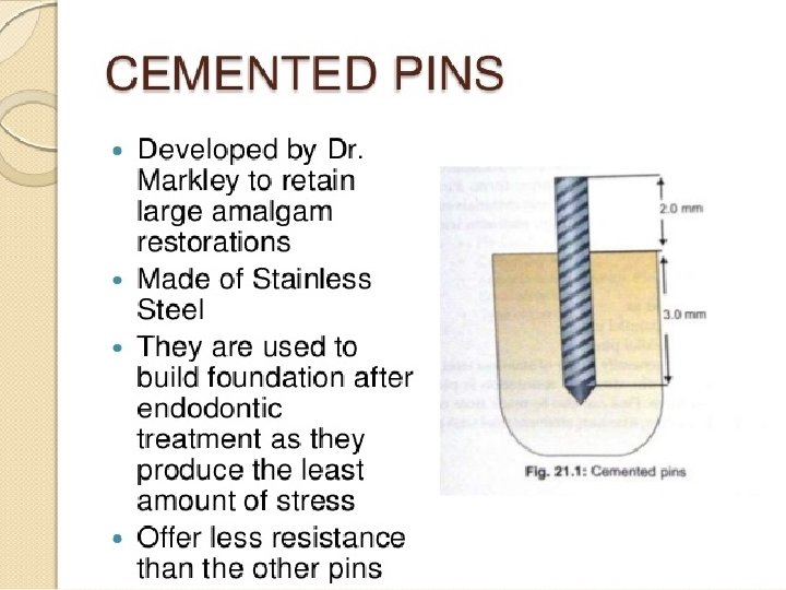
HISTORY In 1958, Dr. Miles Markley introduced a practical instrumentation for the use of a stainless steel cemented pin that resulted in the extensive use of cemented pins in dentistry
DEFINITION Defined as any restoration which requires the placement of one or more pins in dentin to provide to adequate resistance and retention form to the restoration. It has a greater retention than those using boxes or bonding system.
INDICATIONS �Badly broken down or mutilated teeth. �Questionable prognosis-Controlled restoration in tooth with questionable pulp or periodontal prognosis �As a foundation under fixed restoration(core) �Economics �Age and health of the patient
CONTRAINDICATIONS �Occlusal problems �Esthetics-Rarelly used in anterior teeth(Bonding Technique). �Access difficulties-In class V horizontal groove in the gingival & occlusal aspect etc.
ADVANTAGES �Conservation of tooth structure �save time compared with cast restoration. �Greater resistance and retention form �Economics
DISADVANTAGES �Dentinal micro fractures or crazing �Lowered fractured resistance �Strength of amalgam restoration is reduced �Micro leakage around pin �Perforations of pulp or ext. tooth structure. �Difficulty to achieve proper contours
TYPES OF PINS 1. Cemented pins 2. Friction locked pins 3. Self threaded pins
FRICTION LOCKED PINS �Developed by Dr. Goldstein in 1966 �Made of stainless steel �More retentive than cemented pins �Used in vital teeth with good access and ease of tapping/locked the pins �Cause craze lines or cracks �Retain by resilience of dentin
SELF THREADED PINS �Developed by Dr. Going in 1966 �Most popular type among all, the different types and most extensively used pin. �Made of stainless steel or gold plated titanium pins �Provide maximum retention among all types of pins �Cause craze lines �Used in vital teeth
CEMENTED PINS FRICTION LOCKED PINS SELF THREADED PINS Stainless steel with threads or serrations Stainless steel with threads Stainless steel/Titanium with gold plating Pin channel [0. 020” to 0. 32”] larger than pin size [0. 018” to 0. 30”] Pin channel is 0. 001” smaller than pin size Pin channel is 0. 015” to 0. 004” smaller than pin size Luted with standard luting agents Taped into place with Placed by hand mallet wrench or contra angle hand piece Ease of placement Pin placement is difficult Pin placement is easy
CEMENTED PINS FRICTION LOCKED PINS SELF THREADED PINS Less internal stresses Increased internal stresses Least retentive 2 -3 times more retentive than cemented pins 5 -6 times more retentive than friction locked pins
SELF THREADED PINS – THREAD MATE SYSTEM
SELF THREADED PINS – THREAD MATE SYSTEM
REGULAR MINIM MINIKIN MINUTA • Largest diameter pins • Causes maximal stress • Causes maximum dentinal crazing • Rarely used • Next smaller diameter pins • Lesser stress are created • Lesser dentinal crazing • Good retention • Diameter is lesser than minim pins • Very less risk of dentinal crazing • Good retention • MINIM AND MINIKIN ARE COMMONLY USED SIZES OF TMS SYSTEM • SMALLEST SIZE of pins • They are too small to provide adequate retention • Not widely used
PIN DESIGNS
Standard design • 7 mm long • They have flattened heads to fit into the hand wrench or handpiece chuck • After placement the pin is reversed 1/4 th turn to reduce stresses on dentin • Pin height can be adjusted appropriately Self shearing design • Available in varying lengths • They have flattened heads to fit into the hand wrench or handpiece chuck • During pin placement when the pin reaches the bottom of the pin hole, the head automatically shears off, leaving a portion projecting from dentin Two in one design • It consists of 2 pins connected by means of a joint which serves as a shear line for peripheral pin • Total length is 9 mm and 2 pins are about 4 mm each • They have flattened heads to fit into the hand wrench or handpiece chuck • The handpiece need not be reloaded during insertion of more than 1 pin
Link series design • They have a plastic sleeve that fits into the latch type contra angle handpiece or a special plastic hand wrench • Self shearing • Pin engages the dentin and the plastic sleeve can be discarded • Can align well into pin channels Link plus design • Similar to link series design • Self shearing • Available as single or 2 in 1 pins • The major difference in this pin design is that pins have sharper threads and a tapered tip to decrease dentinal stresses while seating
ADVANTAGES OF TMS PINS �Versatile design �Wide range of pin sizes �Color coding allows ease of use �Gold plating eliminates corrosion �Good retention
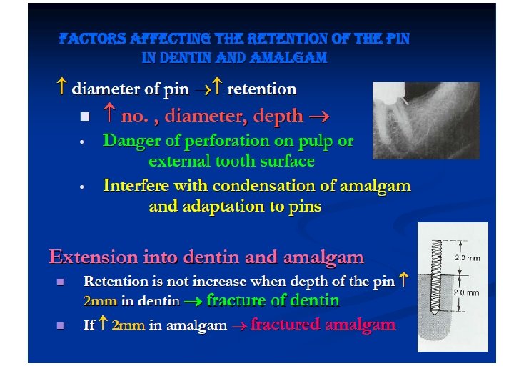
FACTORS AFFECTING THE RETENTION OF THE PIN IN DENTIN AND AMALGAM �Orientation, number and diameter -Non-parallel pin - ↑ retention -Bending of pin – not desirable Interfere with condensation of amalgam Weaker pin, fractured dentin �↑ no. of pin - ↑ retention ↑ crazing & fracture ↓ amount of dentin available ↓ amalgam strength
PIN PLACEMENT 1. MECHANICAL ASPECTS 2. ANATOMICAL ASPECTS 3. MECHANO – ANATOMICAL ASPECTS
MECHANICAL ASPECTS �A] STRESSING CAPABILITIES OF PINS �B] RETENTION OF PINS IN DENTIN �C] MICROCRACKING AND CRAZING
MECHANICAL ASPECTS [PINS AND TOOTH STRUCTURE] A] Stressing capabilities of pins � Type of pins � Diameter of pins � Pin depth and dentinal engagement � Bulk of dentin � Type of dentin
�Shape of pin channels �Loose pins �Irregularly shaped dentinal end of pins �Ratio of dentinal engagement : pin protrusion [ideal 2: 1] �Number of pins in one tooth
�Drill – its use and function �Stresses induced during shortening pins �Retentive features �Inserting pins in stress concentration area of tooth
B] RETENTION OF PINS IN DENTIN �Type of pin �Pin depth and dentinal engagement �Pin channel circumferential shape relative to that of pin �Inter pin distance
�Type of cement �Ratio of dentinal engagement : pin protrusion [ideal 2: 1] �Type of involved dentin �Surface roughness of the pins �Mode of shortening of pins after insertion of pins �Bulk of dentin around the pin
C] MICROCRACKING AND CRAZING �Type of pin �Proximity of pin to DEJ �Induced stresses in involved dentin �Type of dentin
ANATOMICAL ASPECTS �Knowledge of anatomy �Radiograph �Outer surface of tooth �Amount of dentin
MECHANO ANATOMICAL ASPECTS FOR PIN PLACEMENT �Anatomical features �Tooth alignment �Cavity extent �Effect of age or relative age on the pulp chamber
TECHNIQUES FOR INSERTING PINS �Pin channel preparations �Cemented pin technique �Threaded pin technique �Friction grip pin technique
PIN CHANNEL PREPARATION �Twist drill-By using twist drill latch type or depth limiting drill at low speed ( 300 -500) RPM �No. 1/4 round burs- first make pilote hole with round bur to localize position of the pin the complete the hole in one or two thrust( movement) �Apply intermittent pressure
CEMENTED PIN TECHNIQUE INDICATIONS �Ideal technique �Only technique for endodontically treated tooth �Only technique to be used when avaliable location of the pin is close to DEJ
�Ideal technique for a sclerotized / tertiary / calcific barrier / highly demineralized / dehydrated dentin � For class IV restorations �When there is limited bulk of dentin
PROCEDURE �Preparation of pin channel �Checking the surface irregularities of pins �Slow setting phosphate / polycarboxylate introduced by perio explorer tip or lenticulo spiral at slow speed �Placement of pin using lock in or magnetised tweezer or hemostat
�Large amalgam plugger is needed to check the complete seating of the pin �In case of class IV restorations, bending of the pins is to be done before cementation of the pin channel
THREADED PIN TECHNIQUE INDICATIONS �Vital teeth �Dentin to engage the pin is either primary or secondary �Minimum avaliable location is 1. 5 mm from DEJ �If minimum pins are needed for the restoration
PROCEDURE �Preparation of pin channel �Pin is engaged to a driving device and pin is continuously threaded into the pin channel until it offer resistance initiated by the pin channel floor �Desired length of the pin can be cut using small bur and high speed handpiece in the direction of threading and with light intermittent touches �Surface irregularities are corrected �No bending should be performed
FRICTION GRIP PIN TECHNIQUE INDICATIONS �For vital teeth �When bulk of dentin is present [min 4 mm in all 3 dimensions] �Only in the accessible areas
PROCEDURE �Pin channel is prepared �Checking the surface irregularities of pins �Put a colored mark on the pin to indicate the exact depth of the pin channel using a measuring probe �Pin is held in its place at the entrance of the cavity �Concave headed seater is placed on the pin
�With the hammer light strokes are given until that colored mark �Remove all the holding devices �Check for cracks, chipped pieces or grossed fractures
CAVITY PREPARATION �Remove all carious and weakened tooth structure �Initial cavity is prepared with dovetails, boxes, grooves etc �Facial and lingual walls are kept parallel wherever possible �Margins are placed supra-gingivally
�Areas to receive pins should be flat and perpendicular to long axis of the tooth. �There must be enough dentin for pin placement �Weakened cusps should be reduced and occlusal contour should follow the normal contour of the unreduced tooth �PULP PROTECTION
CLASS II DESIGN �Pins should be put in apically deepest and most peripheral parts of the cavity �Pin should not be placed below the cusp �Decreasing the stress concentration on the pin �Use of minimum number of pins with less diameter �Placement of the pin should be such that theres enough restorative material around it
CLASS V DESIGN �Pins are placed axially parallel to the adjacent proximal surface �Pin protrusion should be minimal �Deep retentive grooves are placed �Pins should be placed midway in the preparation but as close to gingival wall as possible
RESTORATION
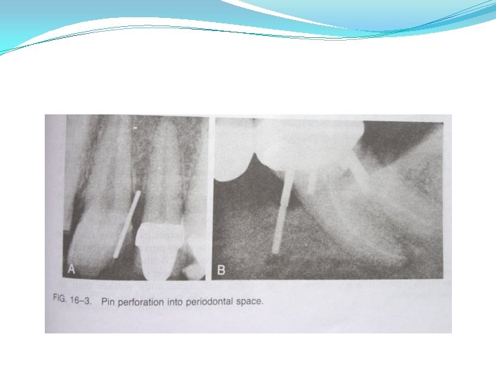
COMPLICATIONS �Drill breakage �Pin breakage �Loose pins �Heat generation �Dentinal cracks �Perforation into pulpal space or external tooth surface
FAILURES
EFFECT OF PINS ON PULP �Generally it responds positively and accepts its presence without any adverse effects �Histologic evaluation reveals inflammatory response, necrotic tissue encapsulation, fibrous tissue regeneration and formation of pre dentin by odontoblasts �Inflammatory reactions have been observed under all kinds of pins
CONCLUSION �The prognosis of the involved tooth and its role in overall treatment plan helps to decide the restoration to be placed �If amalgam is selected as the restorative material to be placed, pins placed in dentin improve the retention of the restoration �Pins have been extensively used in the past to restore such badly broken tooth