PILE FOUNDATION FOR BRIDGES G S YADAV Professor

PILE FOUNDATION FOR BRIDGES G S YADAV Professor, IRICEN 7420041112 gsyadav@iricen. gov. in

BASIC DESIGN PARAMETERS • Design discharge for foundations and protection works • Calculated Depth of scour • Design depth of scour • Soil parameters • Depth of foundation

DESIGN DICHARGE Q • Six Methods : 1. 2. 3. 4. 5. 6. From stream flow records( yearly peak discharges) available for the desired recurrence interval or more Statistical analysis ( if stream flow records are available for less than recurrence interval) Unit hydrograph drawn on basis of limited observations of rainfall and discharge Synthetic unit hydrograph ( 25 km 2 to 2500 km 2) From stage discharge relationships established from gauging of the stream – the design discharge is calculated for known HFL From RDSO report no. RBF 16 for catchment areas less than 25 km 2

DESIGN DISCHARGE FOR FOUNDATION • To provide an adequate margin of safety against an abnormal flood, the Design discharge for foundations Qf , protection works and training works shall be computed by increasing Design Discharge Q as below Catchment Area( Sqkm) Percentage Increase Upto 500 30% 500 upto 5, 000 30% to 20% 5000 to 25, 000 20% to 10% More than 25, 000 Less than 10% ( at the discretion of chief engineer)
 • In case of natural channels flowing in alluvial")
NORMAL DEPTH OF SCOUR (D) • In case of natural channels flowing in alluvial beds where width of waterway provided is not less than Lacey’s regime width D = 0. 473 (Qf / f)1/3 Where ; D is scour depth in meters (depth of eroded bed of river measured from the water level for the discharge Qf) Qf is design discharge for foundation in cumecs f is Lacey’s silt factor (f = 1. 76 √m) m is weighted mean diameter of the bed material particles in mm
 •")
NORMAL DEPTH OF SCOUR (D) •

MAXIMUM DEPTH OF SCOUR Normal depth of scour D is increased to obtain maximum depth of scour for design of foundations, protection works and training works : Nature of river/ location Depth of scour In a straight reach 1. 25 D At the moderate bend conditions e. g. 1. 5 D along apron of guide bund At a severe bend 1. 75 D At a right angle bend or nose of pier 2. 0 D In severe swirls e. g. against mole head of a guide bund 2. 5 D to 2. 75 D

SCOUR DEPTH IN CLAYEY BEDS • In clayey beds, wherever possible , maximum depth of scour shall be assessed from actual observations at site

General Design Principles of Pile foundation • The bottom of foundation shall be taken to such a depth as to provide adequate grip below the deepest anticipated scour • The depth of foundation below the water level for Qf shall not be less than 1. 33 times the maximum depth of scour • The foundation shall not normally rest on sloping rock strata • In calculating foundation pressure, the skin friction( below the deepest scour level) shall also be taken into account except seismic zone IV and V • Dynamic augment need not be considered for design • Minimum grade of concrete to be used in Pile foundations is M 25 (IS 2911/part 1/section 1)
 – BORED (REPLACEMENT PILE)")
CLASSIFICATION OF PILES • BROAD CALSSIFICATION – DRIVEN (DISPLACEMENT PILES) – BORED (REPLACEMENT PILE) • ON THE BASIS OF MATERIAL – TIMBER – STEEL – PCC – RCC – PSC – COMPOSITE

CLASSIFICATION OF PILES • METHOD OF CONSTRUCTION – – DRIVEN PRECAST PILES DRIVEN CAST IN SITU PILES BORED PRECAST PILES BORED CAST IN SITU PILES • MODE OF LOAD TRANSMISSION – END BEARING PILES – FRICTION CUM END BEARING PILES

CLASSIFICATION OF PILES • SECTIONAL AREA – – – CIRCULAR SQUARE TUBULAR OCTAGONAL H-SECTION • SIZE – MICRO (MINI) PILES (<150 mm) – SMALL DIAMETER PILE (>150 mm < 600 mm) – LARGE DIAMETER PILE (>600 mm)
")
CLASSIFICATION OF PILES • INCLINATION – VERTICAL PILES – RAKER (BATTER PILES)

END BEARING PILE

FRICTION PILES

SELECTION OF TYPE OF PILE • Availability of Space : Driven Piles require large areas and head room since it needs larger and heavier driving rigs • Proximity to Structures : driving cause vibrations in ground which may cause damage to nearby structures • Reliability : Precast driven piles ensure good quality of material, uniform section of piles • Compaction of cohesion less soils affected if driven piles are used • Cast in situ piles can be formed to any desired length and no cutting of pile or addition to length required

SOCKETTING IN ROCK • FOR THE END BEARING PILES Ø SOUND RELATIVELY HOMOGENOUS ROCK INCLUDING GRANITE AND GNEISS -- 1 TO 2 D Ø MODERATELY WEATHERED CLOSELY FORMED INCLUDING SCHIST & SLATE ---2 TO 3 D Ø SOFT ROCK --3 TO 4 D

SPACING OF PILES • FOR END BEARING PILES – GOVERNED BY COSISTENCY OF BEARING STRATA – NOT LESS THAN 2. 5 D • FOR FRICTION PILES – SUFFICIENTLY APART TO AVOID OVERLAPPING ZONES – NOT LESS THAN 3 D • MAX SPACING 4 D
 • Pile installation in stiff soil")
INSTALLATION OF PILEs ( BORED CAST in SITU) • Pile installation in stiff soil strata not requiring stabilisation of bore hole : 1. Wide range of piling rigs are now available. Type of rig to be used depends upon type of soil strata and depth of drilling 2. Power driven rotary augur drills are suitable for installing piles in almost all type of soils except where boulders are encountered 3. Piles can be installed from 300 mm dia to over 5000 mm dia and depths upto 100 m
 • Pile installation in soil strata")
INSTALLATION OF PILEs ( BORED CAST in SITU) • Pile installation in soil strata requiring stabilisation of bore hole : 1. One option could be to drive MS casing up to full depth. 2. Mud circulation method ( bentonite slurry or polymer based slurry) 3. Continuous Flight Augers ( CFA) method

Rotary Drilling • The bore hole is advanced by a drill bit, fixed to lower end of the drill rods and rotated by a suitable chuck. It is always kept in firm contact with the bottom of the hole. • The broken rock/soil fragments are removed by circulating water or drilling mud (bentonite slurry/polymer based slurry) pumped through the drill rods and up through the bore hole from which it is collected in a settling tank for recirculation. • The bentonite slurry stabilizes the bore hole, hence no casing is required.

Percussion Drilling • In percussion drilling, bore hole is advanced by alternatively lifting and dropping a heavy drilling bit. Water is added to the hole during boring, if not already present and the slurry of pulverised material is bailed out at intervals. • The slurry is removed using bailers and sand pumps. Change in soil character is identified by the composition of the outgoing slurry. • It can be used in most of the soils and rocks and can drill any material.
 1. Hollow stem CFA are commonly used in US and")
Continuous Flight Augers (CFA) 1. Hollow stem CFA are commonly used in US and Europe for constructing cast in situ piles 2. The augur is drilled into the soil up to design depths 3. Augur is then slowly removed with drilled soil as concrete is pumped through the hollow stem 4. Reinforcing steel is then is lowered into wet column Hollow Stem CFA

TREMIE CONCRETING

TREMIE CONCRETING • Tremie concrete placement method uses a pipe , through which concrete is placed below water level • The lower end of pipe is kept immersed in fresh concrete by about 1 m, so that the rising concrete from the bottom displaces the water without washing out the cement content • Tremie pipe shall not be less than 200 mm in diameter and strong enough to withstand external pressure of the water in which it is suspended, even if a partial vacuum develops inside the pipe

Tremie Concrete Mix • Special mix with plasticizer to get workability of about 140 -180 mm slump • Set retarders may also be used • Smaller aggregate sizes for easy flow-ability of concrete • Designed for placement under water • WC ratio 0. 42 ( max 0. 45) • Air entrainment admixtures to give about 6% total air

LOAD CARRYING CAPACITY OF PILE • Ultimate load carrying capacity of a Pile may be assessed by : (i) Dynamic pile formula, using data obtained during driving of piles, or by (ii) Static formula…… on the basis of soil test results, or by (iii) Load Test ……only after 4 weeks of installation of pile • For Non cohesive soils Hiley’s Formula is more reliable than other formulae ( Appendix B of IS 2911 pt 1/sec 1) • Hiley’s Formula not reliable in cohesive soils • Where scour is anticipated , resistance due to skin friction will be available only below scour level ( the skin friction shall be ignored in seismic zones IV and V) • When pile is installed through compressive fill or sensitive clay into underlying hard stratum, a downward drag down force is generated in the fill. This must be added to the load

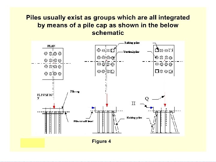
FACTORS INFLUENCING PILE CAPACITY • • • SURROUNDING SOIL INSTALLATION TECHNIQUE SPACING OF PILES SYMMETRY OF THE GROUP LOCATION OF PILE CAP DRAINAGE CONDITIONS IN SOIL
")
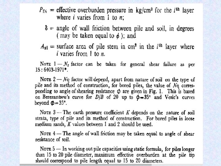
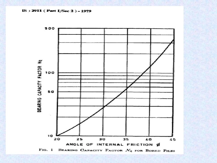
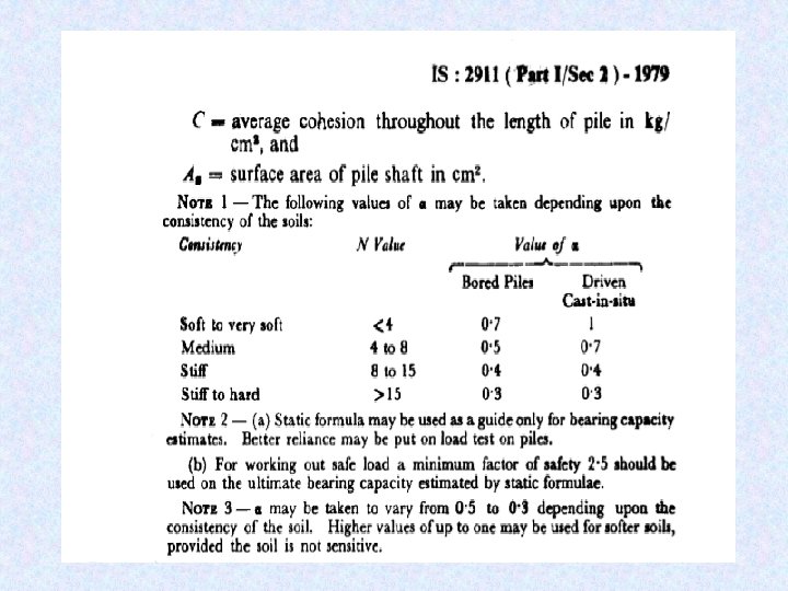
(Appendix B IS 2911 pt 1/sec 2)
")
(Appendix B IS 2911 pt 1/sec 2)

BEARING CAPACITY OF A PILE GROUP • MAY BE ØEQUAL TO THE BC OF SINGLE PILE X NO. OF PILES ØLESS/MORE THAN THE ABOVE • FRICTION PILES, CAST OR DRIVEN INTO PROGRESSIVELY STIFFER MATERIALS & END BEARING PILES – EQUAL • FRICTION PILES INSTALLED IN SOFT AND CLAYEY SOILS – LESS • DRIVEN PILES IN LOOSE SANDY SOILS – MORE DUE TO EFFECT OF COMPACTION
")
BEARING CAPACITY OF A PILE GROUP (para 2. 6 of well& pile foundation code) STRATA TYPE OF PILE BC PF PILE GROUP 1. DENSE SAND NOT UNDERLAIN BY WEAK DEPOSITS DRIVEN NO. OF PILES X SPC* 2. LOOSE SANDY SOILS 3. SAND NOT UNDERLAIN BY WEAK DEPOSITS ½ (NO. OF PILES X SPC*) BORED *SPC – SINGLE PILE CAPACITY ⅔ (NO. OF PILES X SPC*)

PERMISIBLE TOLERANCE FOR PILES • ALIGNMENT CONTROL – VERTICAL PILES – DEVIATION OF 1. 5% – RAKER PILES – DEVIATION OF 4% • SHIFT – FOR PILES LESS THAN OR EQUAL TO 600 MM DIA • NOT MORE THAN 75 MM OR D/4 WHICHEVER IS LESS – FOR MORE THAN 600 MM. DIA. PILES • 75 MM OR D/10 WHICHEVER IS MORE • EXCESS DEVIATION BEYOND DESIGN LIMITS –PILE TO BE REPLACED OR SUPPLEMENTED BY ADDITIONAL PILES

PILE LOAD TEST • Two types of tests for each type of loading ( ie vertical, lateral, pullout ) Ø Initial test, & Ø Routine test
 • Initial Test § For small size projects (")
PILE LOAD TESTING (IS-2911 PART-IV) • Initial Test § For small size projects ( total piles less than 1000) , a minimum of two tests § For large projects ( piles more than 1000), a minimum of two tests for first 1000 piles and additional one test for every additional 1000 piles and part thereof § Initial test piles should be installed by the same technique, same type of equipment as that proposed for working piles § The test load in initial test shall not be less than 2. 5 times the estimated safe load § Initial pile load test shall preferably be carried out before taking up the piling job
 • Purpose of Initial Load Test § Arrive at")
PILE LOAD TESTING (IS-2911 PART-IV) • Purpose of Initial Load Test § Arrive at safe load by applying FOS on ultimate load capacity determined from tests § To provide guidelines for setting up limits for acceptance of routine tests § To have a check on safe load calculated by static or dynamic formulae
 • Routine Test – On 0. 5 percent of")
PILE LOAD TESTING (IS-2911 PART-IV) • Routine Test – On 0. 5 percent of total number piles subject to a minimum one test, can be increased to 2% depending on nature of strata. • Purpose – It is carried out on a working pile with a view to check whether pile is capable of taking the working load assigned to it – Detection of any unusual performance contrary to the findings of initial test. – Workmanship
 • The piles to be tested for routine test")
PILE LOAD TESTING (IS-2911 PART-IV) • The piles to be tested for routine test may be selected on the basis of the following: 1. Abnormal variation in concrete consumption 2. Sudden drop in concrete level during construction of pile 3. Problem encountered during boring and tremie operation 4. Significant variation in depth of pile with respect to adjacent piles and boring record 5. Anomalies observed during driving operation in case of driven piles 6. Piles under sensitive location of structures 7. Any doubts arrived during non-destructive tests
 • In cases where upper part of the pile")
PILE LOAD TESTING (IS-2911 PART-IV) • In cases where upper part of the pile is likely to be exposed later on due to scour, liquefaction or otherwise then capacity contributed by that portion of pile during load test shall be duly accounted for or simulated by provision of larger dia casing around the pile up to scour depth • Generally load application and deflection measurement shall be done at pile top • The test should be carried at cut off level where practicable, otherwise suitable allowance shall be made in interpretation of test results

PILE LOAD TESTING METHODS • Maintained Load Method : applicable for both initial and routine test • Cyclic Method : this method is used in case of initial test to find out separately skin friction and point bearing load on single piles • CRP Method : this method is used for initial test only

MAINTAINED LOAD METHOD • Test should be carried out by applying a series of vertical downward incremental load, each increment being about 20 percent of safe estimated load on pile • Each stage of loading shall be maintained till the rate of movement of the pile top is not more than 0. 2 mm/h or until 2 h have elapsed, whichever is earlier subject to a minimum of 1 h • The test load is maintained for 24 hours

MAINTAINED LOAD METHOD • Vertical loading on single pile shall be continued till one of the following takes place : (a) In case of Initial Load Test: 1. Applied load reaches 2. 5 times the safe estimated load; or 2. Max settlement of pile exceeds a value of 10 percent of pile diameter in case of uniform dia piles and 7. 5 percent in case of bulb dia of under-reamed piles.
 In case of routine load test : 1. Applied load")
MAINTAINED LOAD METHOD (b) In case of routine load test : 1. Applied load reaches 1. 5 times the working load ; or 2. Max settlement of pile exceeds a value of 12 mm for piles dia up to and including 600 mm and 18 mm or maximum of 2 percent of pile dia whichever is less for piles of dia more than 600 mm.

MAINTAINED LOAD METHOD • Vertical loading on group of piles shall be continued till one of the following takes place : (a) In case of initial load test: 1. Applied load reaches 2. 5 times the safe estimated load ; or 2. Maximum settlement of pile exceeds a value of 40 mm (b) In case of routine load test : 1. Applied load reaches the working load 2. Maximum settlement of pile exceeds a value of 25 mm

SAFE LOAD-INITIAL TEST • THE SAFE LOAD ON A SINGLE PILE WILL BE LEAST OF THE FOLLOWING • (A) FOR PILES UPTO 600 MM DIA : – Two third of the final load at which total displacement attains a value of 12 mm – 50 % of the final load at which the total displacemnt equals 10 % of the dia. Of pile for uniform dia piles and 7. 5 percent of bulb dia for under-reamed piles.
 FOR PILES MORE THAN 600 MM DIA : 1. Two-thirds")
SAFE LOAD-INITIAL TEST (B) FOR PILES MORE THAN 600 MM DIA : 1. Two-thirds of the final load at which the total displacement attains a value of 18 mm or maximum of 2 percent pile diameter whichever is less. 1. 50 % of the final load at which the total displacemnt equals 10 % of the dia. Of pile for uniform dia piles and 7. 5 percent of bulb dia for under-reamed piles.

LOAD SETTLEMENT CURVE SAFE LOAD Least of 2/3 P 1 or ½ P 2

SAFE LOAD – INITIAL TEST • THE SAFE LOAD FOR GROUP OF PILES – FINAL LOAD AT WHICH TOTAL DISPLACEMENT IS 25 MM – TWO THIRD OF FINAL LOAD AT WHICH DISPLACEMENT IS 40 MM

ACCEPTANCE CRITERIA FOR ROUTINE TEST 1. The routine test shall be carried out for a test load of at least 1. 5 times the working load ; 2. The maximum settlement at the load being not greater than 12 mm for piles up to 600 mm dia , and 3. 18 mm or 2 percent of pile dia whichlever less for piles of dia more than 600 mm

OVERLOADING OF PILES • 10% of the pile capacity may be allowed on each pile • Max overloading on a group shall be restricted to 40% of the allowable load on a single pile • Shall not be allowed at initial design stage
")
STATIC LOAD TEST ( Maintained Load Method)
")
PILE LOAD TEST (KENTELEDGE ARRANGEMENT)
")
PILE LOAD TEST (WITH ANCHOR PILES)

DEFECTS IN CAST IN SITU PILES • HONEY COMBING DUE TO INADEQUATE VIBRATIONS • SEGREGATION DUE TO IMPROPER CONCRETE PLACEMENT METHODS • WASHOUT OF CEMENT DUE TO GROUNDWATER FLOW • CRACKS IN PILE SHAFT DUE TO SHRINKAGE • INCLUSION OF FOREIGN MATERIAL • NECKING DUE TO COLLAPSE OF SIDE WALLS DURING WITHDRAWAL OF TEMPORARY CASING
 • • For a successful pile foundation it")
INTEGRITY TEST ON PILES (IS 14893) • • For a successful pile foundation it is imperative that the piles constructed are of sound quality and of design shape and dimensions The routine vertical load tests carried out on working piles do not provide direct evidence of structural integrity of Piles Also, in view of very limited number of tests ( 0. 5% to 2%) at a project site it is not possible to reliably testify structural quality of piles It is also true that all the piles can not be tested by load testing on account of cost and time Cast-in-situ piles in majority of cases fail due to defects in pile shaft such as necking, discontinuity of concrete , intrusion of foreign matter and improper toe formation due to contamination of concrete at base with soil particles etc. In pre-cast piles also cracks can develop during handling and installation If pile integrity can be assessed before completion of pile caps then it will go a long way in assuring integrity of pile foundations

INTEGRITY TEST ON PILES • NDT methods have been developed and standardised for checking integrity of piles and becoming important tool for evaluation of quality and acceptance of pile foundations • However, these NDT methods can’t be replacement of prescribed load testing of piles • Integrity testing is relatively simple and quick and enables number of piles to be examined in a day • Methods don't identify all imperfections in piles but gives useful information about continuity, defects such as cracks, necking, soil intrusions, changes in cross section and approximate pile lengths • Integrity tests should, however, be done by the experienced person who has sufficient training and skill in testing and interpretation of results • It is for engineers to decide whether results of tests point to presence of significant defects that may materially affect the long term load carrying capacity of piles • Rejection of piles may not be only on the basis of integrity tests alone and may be followed by load testing and where possible examined by excavation

INTEGRITY TEST ON PILES IS 14893

INTEGRITY TEST METHODS • Various methods are available for checking integrity of piles after installation • In the most widely used method impulses or vibrations are applied to top of pile and measurements made of the timings and attenuation of reflected signals • Methods based upon one dimensional stress based approach known as Sonic Integrity testing have found wide acceptance • Low strain integrity testing, a Sonic integrity method has found wide acceptance in India

LOW STRAIN INTEGRITY TESTING • A low stress wave is imparted to the pile shaft by tapping it with small metal/hard rubber hammer • The shock travelling down the shaft is reflected back from the pile toe or from any discontinuity due to change in density and recorded through a suitable transducer/ accelerator

LOW STRAIN INTEGRITY TESTING- PRINCIPLE

RELEVENT STANDARDS • Manual on the Design and Construction of well and pile Foundations issued by RDSO • IS 2911 - Part I – Section I – Driven cast in situ piles – Section II- Bored cast in situ piles – Section III- Driven precast concrete piles • IS 2911 - Part IV- Load test

RELEVENT STANDARDS • Concrete Bridge code- For structural design • IRC- 78 - For Road bridge foundations, can be referred for guidance • IS 14893 – NDT on Piles

STEPS OF DESIGN 1. From soil data, depth of scour – fix length of pile 2. Based on thumb rules, fix dia of pile 3. Calculate load carrying capacity of single pile using static formulae 4. Do rough design for selected group of piles. Spacing to be based on thumb rules 5. Check design for load carrying capacity, settlement, depth etc. 6. Revise design if required 7. Conduct load test to confirm capacity of pile

H T N A Y K U O

IMP. CODAL PROVISIONS • DIA. OF PILE – Bridge Manual- > normally 1 m – IRC-78 » » – IS 2911 - Part I, Section 2 » • Bored piles on land- min. 1 m Bored pile in river bridge- min. 1. 2 m Provisions are for max. dia of 2. 5 m For Railway bridges dia. Of 1 m to 1. 5 m be normally adopted

IMP. CODAL PROVISIONS SPACING OF PILE • – IRC-78 » » – – • Friction- min. 3 D End bearing- Can be reduced to clear distance= D that is c/c 2 D IS 2911 - Part I, Section 2 » » » End bearing- hard soil- Min. 2. 5 D End bearing- hard rock- Min. 2. 0 D Friction- Min 3. 0 D » » » Friction – min. 3 D End bearing- Min. 2. 5 D Max. 4 D RDSO Manual For Railway bridges spacing of 2. 5 D to 3. 5 D be normally adopted

IMP. CODAL PROVISIONS GROUP BEHAVIOR • – IRC-78 » » – IS 2911 - Part I, Section 2 » » – End bearing- If spacing > 2. 5 D, no reduction Friction- If spacing > 3 D, no reduction Check for block failure Settlement of group/single pile given for different width of group/pile dia Bored piles- end bearing- No reduction Other cases – descriptive guidelines given RDSO Manual » » » Dense sand not underlying by weak soil – driven pile – No reduction Loose sand soil – 50% reduction Sand not underlying by weak soil – boredreduction 33%

IMP. CODAL PROVISIONS • PILE CAP – IRC-78 » » » – IS 2911 - Part I, Section 2 » » – Min. thickness 0. 6 m or 1. 5 times dia of pile, whichever is more max offset of 150 mm beyond outer face Pile to project 50 mm into pile cap Offset of 100 -150 mm beyond outer face Pile to project 50 mm into pile cap Should be rigid enough Can be designed by taking dispersion at 45 degrees both from substructure and pile upto centre line RDSO Manual » NIL

IMP. CODAL PROVISIONS CONCRETE AND STEEL • – IRC-78 » » » – IS 2911 - Part I, Section 2 » M 20, Min. cement 400 kg/m 3, 10% extra cement when under water, slump 100 - 180 mm (150 -180 for tremie) Min. long reinforcement 0. 4%, Min. spacing 100 mm, links min 6 mm @ 150 mm c/c. Min cover 40 mm. » » NIL CBC to be followed based on environment condition » » – M 35, Min. cement 400 kg/m 3, Max. W/C 0. 4, slump 50 mm (150 -200 for tremie) Min. long reinforcement 0. 4%, links min. 8 mm @ 150 mm c/c. Min cover 75 mm. RDSO Manual

IMP. CODAL PROVISIONS • FOS – IRC-78 » 2. 5 if derived from static formulae for soil. 5 for end bearing on rock and 10 for socket resistance. – IS 2911 - Part I, Section 2 » Appendix given for calculating strength with static formulae – RDSO Manual » 3 if derived from static formulae. » 2 if derived from load test

LAYOUT q Accuracy of prime importance q Should always be cross checked by at least two independent surveys q Permanent theodolite stations with the base line on the bank will be established to mark reference points

CAISSONS • In case where the velocity of water in the river is high making it difficult to construct either an island or cofferdam to construct a well, caisson type construction has been used. • The caisson is pre cast at the shore with the bottom which is generally provided with openings which are plugged, and toed to the required position by tugs and then plugs are removed to permit the caisson to reach the bottom of the ocean bed. • Sinking can also be by concreting in pockets

CAISSONS Example of caisson foundation in India are Ganga bridge at Mokameh, Brahmaputra bridge in Assam Mahanadi Bridge at Cuttack

Well v/s Pile v Wells have a large cross sectional area and hence more bearing capacity of soil. v q=5. 4 N 2 B + 16(100+N 2)D v Well are hallow and most of the material is at periphery. This provides a large section modulus. v Useful in controlling deflection against high horizontal force v it is possible to sink a well through soil having boulders, logs of wood, whereas Piles can not be driven

Well v/s Pile v In case of wells, it is possible to visually examine the strata through which sinking is done and material on which it is finally resting, hence the bearing capacity of a well is certain. On other hand bearing capacity of pile is generally uncertain v Concreting in the staining of wells is done under dry conditions and the quality of concrete is much better than in case of cast in situ piles.

Well v/s Pile v Size of well foundation cannot be reduced indefinitely and hence it uneconomical to use well foundation for very small loads, pile foundations are more suitable.

H T N A Y K U O
- Slides: 81