Picture Perfect RGB Rendering Using Spectral Prefiltering and

Picture Perfect RGB Rendering Using Spectral Prefiltering and Sharp Color Primaries Greg Ward Exponent - Failure Analysis Assoc. Elena Eydelberg-Vileshin Stanford University Presented at the 13 th Eurographics Workshop on Rendering in Pisa, Italy, June 2002
")
Talk Overview Color Rendering Techniques 2. Getting the Most Out of RGB 1. a) b) Spectral prefiltering The von Kries white point transform Three Tristimulus Spaces 4. Experimental Results 5. Conclusions 3.

1. A Brief Comparison of Color Rendering Techniques n Spectral Rendering üN spectrally pure samples n Component Rendering üM vector basis functions n RGB (Tristimulus) Rendering ü Tristimulus value calculations

Spectral Rendering 1. 2. 3. Divide visible spectrum into N wavelength samples Process spectral samples separately throughout rendering calculation Compute final display color using CIE color matching functions and standard transformations
![Component Rendering [Peercy ‘ 93 SIGGRAPH] 1. 2. 3. Divide visible spectrum into M](http://slidetodoc.com/presentation_image/1362f23ba4e156b2a4ddfb2f5ee7043b/image-5.jpg "Component Rendering [Peercy ‘ 93 SIGGRAPH] 1. 2. 3. Divide visible spectrum into M")
Component Rendering [Peercy ‘ 93 SIGGRAPH] 1. 2. 3. Divide visible spectrum into M vector bases using component analysis Process colors using Mx. M matrix multiplication at each interaction Compute final display color with 3 x. M matrix transform
 Rendering Precompute tristimulus values 2. Process 3 samples separately throughout rendering calculation")
RGB (Tristimulus) Rendering Precompute tristimulus values 2. Process 3 samples separately throughout rendering calculation 3. Compute final display color with 3 x 3 matrix transform (if necessary) 1.

Rendering Cost Comparison Pre. Multiplies / Postprocessing Interaction processing Spectral None Component Vector analysis RGB Little or none N (N 9) Mx. M (M 3) 3 N multiplies per pixel 3 M per pixel 0 to 9 per pixel

Strengths and Weaknesses Strengths Weaknesses Spectral Potential accuracy Cost, aliasing, data mixing Component Optimizes cost/benefit Preprocessing requirements RGB Fast, widely supported Limited accuracy
![Spectral Aliasing Cool white fluorescent spectrum [Meyer 88] suffers worse with only 4 samples](http://slidetodoc.com/presentation_image/1362f23ba4e156b2a4ddfb2f5ee7043b/image-9.jpg "Spectral Aliasing Cool white fluorescent spectrum [Meyer 88] suffers worse with only 4 samples")
Spectral Aliasing Cool white fluorescent spectrum [Meyer 88] suffers worse with only 4 samples

The Data Mixing Problem n Typical situation: n n Illuminants known to 5 nm resolution Some reflectances known to 10 nm Other reflectances given as tristimulus Two alternatives: A. B. Reduce all spectra to lowest resolution Interpolate/synthesize spectra [Smits ‘ 99]

2. Getting the Most Out of RGB A. B. C. D. E. How Does RGB Rendering Work and When Does It Not? Can RGB Accuracy Be Improved? Useful Observations Spectral Prefiltering The von Kries White Point Transform
=(1,")
Status Quo Rendering n White Light Sources n E. g. , (R, G, B)=(1, 1, 1) n RGB material colors obtained by dubious means n E. g. , “That looks pretty good. ” ü This actually works for fictional scenes! n Color correction with ICC profile if at all

When Does RGB Rendering Normally Fail? n When you start with measured colors n When you want to simulate color appearance under another illuminant n When your illuminant and surface spectra have sharp peaks and valleys The Result: Wrong COLORS!
 Naïve tristimulus rendering (CIE XYZ)")
Full spectral rendering (Fluorescent source) Naïve tristimulus rendering (CIE XYZ)

Given Its Predominance, Can We Improve RGB Rendering? n Identify and minimize sources of error Source-surface interactions n Choice of rendering primaries n n Overcome ignorance and inertia Many people render in RGB without really understanding what it means n White-balance problem scares casual users away from colored illuminants n

A Few Useful Observations 1. 2. 3. Direct illumination is the first order in any rendering calculation Most scenes contain a single, dominant illuminant spectrum Scenes with mixed illuminants will have a color cast regardless Conclusion: Optimize for the Direct Diffuse Case
 b) Prefilter material spectra")
Picture Perfect RGB Rendering 1. Identify dominant illuminant spectrum a) b) Prefilter material spectra to obtain tristimulus colors for rendering Adjust source colors appropriately Perform tristimulus (RGB) rendering 3. Apply white balance transform and convert pixels to display color space 2.

Spectral Prefiltering To obtain a tristimulus color, you must know the illuminant spectrum XYZ may then be transformed by 3 3 matrix to any linear tristimulus space (e. g. , s. RGB)

Prefiltering vs. Full Spectral Rendering Prefiltering performed once per material vs. every rendering interaction + Spectral aliasing and data mixing problems disappear with prefiltering - However, mixed illuminants and interreflections not computed exactly Regardless which technique you use, remember to apply white balance to result! +

Quick Comparison Full spectral, no white balance Prefiltered RGB, no white balance Full spectral, white balanced Prefiltered RGB, white balanced

Where: Transform for The von Kries Chromatic Adaptation The von Kries transform takes colors from absolute XYZ to adapted equiv. XYZ’ Display white point Scene white point

Chromatic Adaptation Matrix n The matrix MC transforms XYZ into an “adaptation color space” n Finding the optimal CAM is an underconstrained problem -- many candidates have been suggested n “Sharper” color spaces tend to perform better, and seem to be more “plausible” [Susstrunk 2001] [Finlayson 2001]
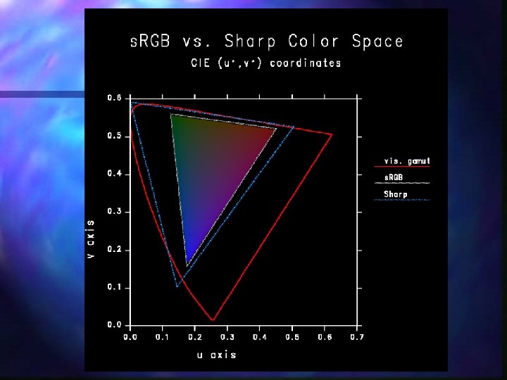

3. Three Tristimulus Spaces for Color Rendering n CIE XYZ Covers visible gamut with positive values n Well-tested standard for color-matching n n s. RGB Common standard for image encoding n Matches typical CRT display primaries n n Sharp RGB n Developed for chromatic adaptation

XYZ Rendering Process 1. Apply prefiltering equation to get absolute XYZ colors for each material a) Divide materials by illuminant: b) Use absolute XYZ colors for sources Render using tristimulus method 3. Finish w/ CAM and display conversion 2.

s. RGB Rendering Process 1. Perform prefiltering and von Kries transform on material colors a) b) Model dominant light sources as neutral For spectrally distinct light sources use: Render using tristimulus method 3. Resultant image is s. RGB 2.

Sharp RGB Rendering Process 1. Prefilter material colors and apply von Kries transform to Sharp RGB space: Render using tristimulus method 3. Finish up CAM and convert to display 2.

Our Experimental Test Scene Tungsten source Macbeth Red Fluorescent source Macbeth Neutral. 8 Macbeth Green Gold Macbeth Blue. Flower

4. Experimental Results n Three lighting conditions n n Three rendering methods n n Single 2856°K tungsten light source Single cool white fluorescent light source Both light sources (tungsten & fluorescent) Naïve RGB (assumes equal-energy white) Picture Perfect RGB Full spectral rendering (380 to 720 nm / 69 samp. ) Three color spaces (XYZ, s. RGB, Sharp RGB)
 Full spectral Naive Picture Perfect CIE 1998 E* of 5")
Example Comparison (s. RGB) Full spectral Naive Picture Perfect CIE 1998 E* of 5 or above is visible in side-by-side comparisons

E* Error Percentiles for All Experiments

Results Summary n Prefiltering has ~1/6 the error of naïve rendering for single dominant illuminant n Prefiltering errors similar to naïve in scenes with strongly mixed illuminants n CIE XYZ color space has 3 times the rendering errors of s. RGB on average n Sharp RGB rendering space reduces errors to 1/3 that of s. RGB on average

5. Conclusions n Prefiltering is simple and practically free n Avoids aliasing and data mixing problems of full spectral rendering n Error comparable to 3 component rendering [Peercy 93] at 1/3 the cost n Mixed illuminants and specular reflections no worse than naïve RGB

Future Work n Test on a wider variety of scenes n Study best approach for colored, specular materials (i. e. , metals) n Investigate behavior in scenes where indirect illumination dominates
- Slides: 34