
PIC MCU Safety Features and Certified Class B

PIC® MCU Safety Features and Certified Class B Library
Software and Hardware Support Microchip’s library of low-level software routines simplifies IEC 60730 compliance for Class B Safety. Microchip also provides products with integrated safety features to ease implementation. 2
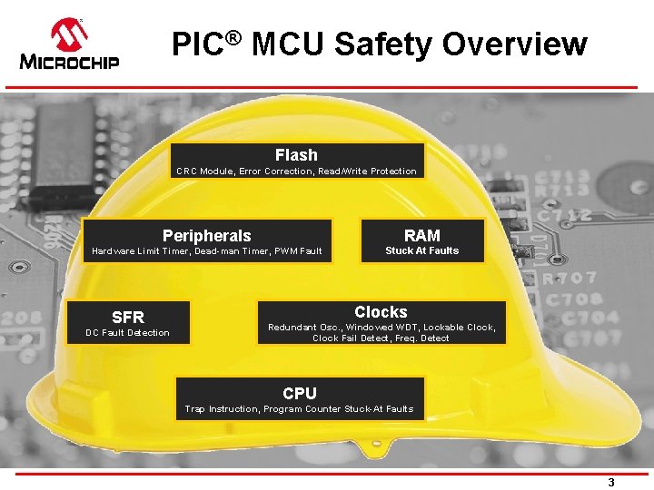
PIC® MCU Safety Overview Flash CRC Module, Error Correction, Read/Write Protection Peripherals RAM Hardware Limit Timer, Dead-man Timer, PWM Fault Stuck At Faults SFR DC Fault Detection Clocks Redundant Osc. , Windowed WDT, Lockable Clock, Clock Fail Detect, Freq. Detect CPU Trap Instruction, Program Counter Stuck-At Faults 3
Agenda 8 -bit MCU Safety Features 16 -bit MCU & DSC Safety Features 32 -bit MCU Safety Features Certified Class B Library 4

8 -bit MCU Safety Features
Software and Hardware Support Cyclic Redundancy Check with Memory scan (CRC/SCAN) Adds reliability by scanning program memory for corruption Detection done in hardware, no interruption to the CPU Software configurable 6
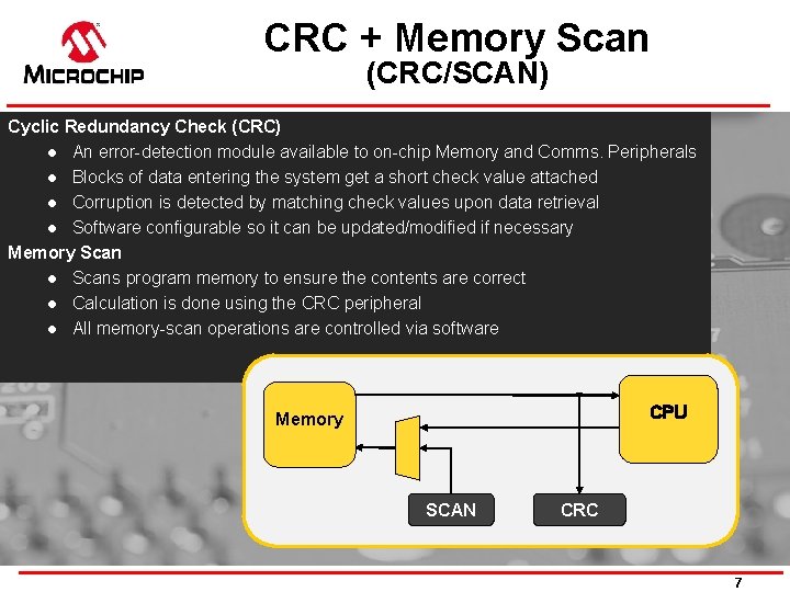
CRC + Memory Scan (CRC/SCAN) Cyclic Redundancy Check (CRC) l An error-detection module available to on-chip Memory and Comms. Peripherals l Blocks of data entering the system get a short check value attached l Corruption is detected by matching check values upon data retrieval l Software configurable so it can be updated/modified if necessary Memory Scan l Scans program memory to ensure the contents are correct l Calculation is done using the CRC peripheral l All memory-scan operations are controlled via software CPU Memory SCAN CRC 7

Software and Hardware Support Windowed Watchdog Timer (WWDT) Monitors software to ensure operation within predefined limits A RESET is generated when instructions fall outside a set window Offloads timing-critical tasks from CPU 8
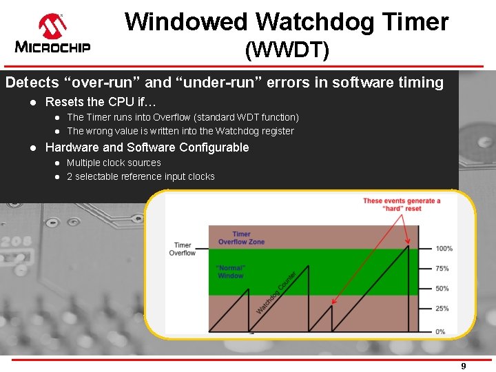
Windowed Watchdog Timer (WWDT) Detects “over-run” and “under-run” errors in software timing l Resets the CPU if… l l l The Timer runs into Overflow (standard WDT function) The wrong value is written into the Watchdog register Hardware and Software Configurable l l Multiple clock sources 2 selectable reference input clocks 9
Software and Hardware Support Hardware Limit Timer (HLT) Detects hardware fault conditions (stall, stops, etc. ) Ideal for closed-loop control applications Eliminates the need for external devices Multiple modes and clock sources adds design flexibility 10
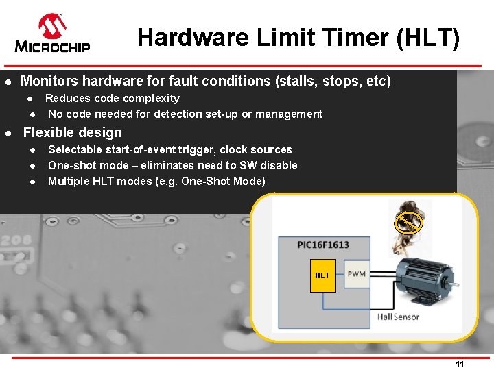
Hardware Limit Timer (HLT) l Monitors hardware for fault conditions (stalls, stops, etc) l l l Reduces code complexity No code needed for detection set-up or management Flexible design l l l Selectable start-of-event trigger, clock sources One-shot mode – eliminates need to SW disable Multiple HLT modes (e. g. One-Shot Mode) HLT 11
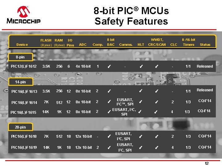
8 -bit PIC® MCUs Safety Features FLASH RAM Device I/O (Bytes) Pins ADC Comp. 8 -bit DAC Comms. HLT WWDT, CRC/SCAN CLC 8 -/16 -bit Timers Status 8 -pin PIC 12(L)F 1612 3. 5 K 256 6 4 x 10 -bit 1 ✓ - ✓ ✓ - 1/1 Released PIC 16(L)F 1613 3. 5 K 256 12 8 x 10 -bit 2 ✓ - ✓ ✓ - 1/1 Released PIC 16(L)F 1614 7 K 512 12 8 x 10 -bit 2 ✓ EUSART, I 2 C™, SPI ✓ ✓ 2 1/3 CQ 4’ 14 PIC 16(L)F 1615 14 K 1 K 12 8 x 10 -bit 2 ✓ EUSART, I 2 C, ✓ SPI ✓ 4 1/3 CQ 4’ 14 PIC 16(L)F 1618 7 K 512 18 12 x 10 -bit - ✓ ✓ ✓ 2 1/3 CQ 4’ 14 PIC 16(L)F 1619 14 K 1 K 18 12 x 10 -bit 2 ✓ ✓ ✓ 4 1/3 CQ 4’ 14 14 -pin 20 -pin EUSART, I 2 C, SPI 12
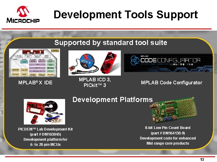
Development Tools Supported by standard tool suite MPLAB ICD 3, PICkit™ 3 MPLAB® X IDE MPLAB Code Configurator Development Platforms PICDEM™ Lab Development Kit (part # DM 163045) Development platform for 6 - to 20 -pin MCUs 8 -bit Low Pin Count Board (part # DM 164130 -9) Development code for enhanced Mid-range core products 13

16 -bit MCU Safety Features
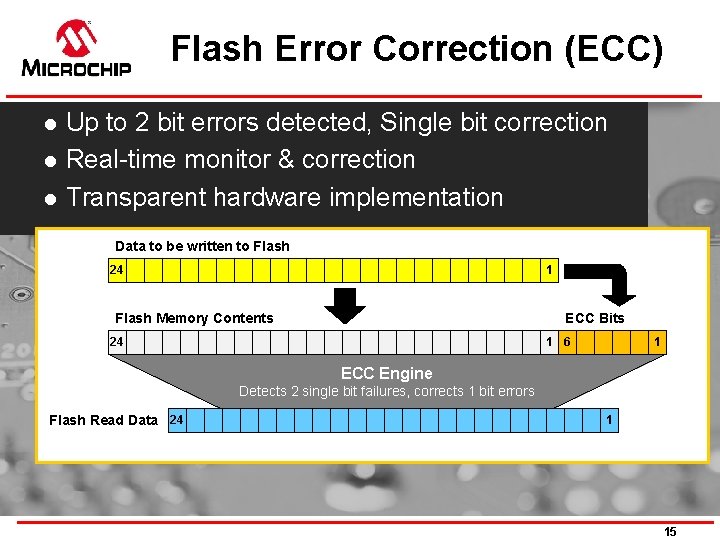
Flash Error Correction (ECC) l l l Up to 2 bit errors detected, Single bit correction Real-time monitor & correction Transparent hardware implementation Data to be written to Flash 24 1 Flash Memory Contents ECC Bits 24 1 6 1 ECC Engine Detects 2 single bit failures, corrects 1 bit errors Flash Read Data 24 1 15
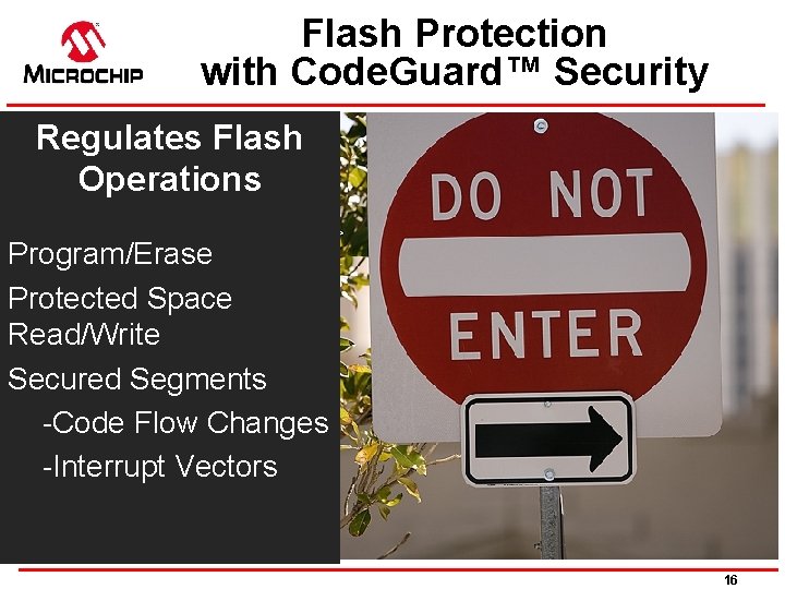
Flash Protection with Code. Guard™ Security Regulates Flash Operations Program/Erase Protected Space Read/Write Secured Segments -Code Flow Changes -Interrupt Vectors 16
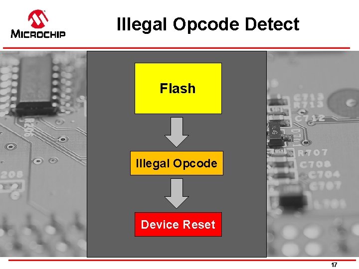
Illegal Opcode Detect Flash Illegal Opcode Device Reset 17
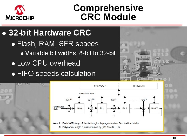
Comprehensive CRC Module l 32 -bit Hardware CRC l Flash, RAM, SFR spaces l Variable bit widths, 8 -bit to 32 -bit Low CPU overhead l FIFO speeds calculation l 18
Error Trap Monitor Generate Reset if simultaneous Traps occur TRA P A R PT 19
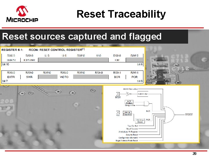
Reset Traceability Reset sources captured and flagged 20
OSCCON Lock Sequence Password sequence l l l Prevents errant frequency changes Requires two back to back writes Separate upper and lower byte writes l l Upper byte is oscillator source Lower byte is oscillator enable 21
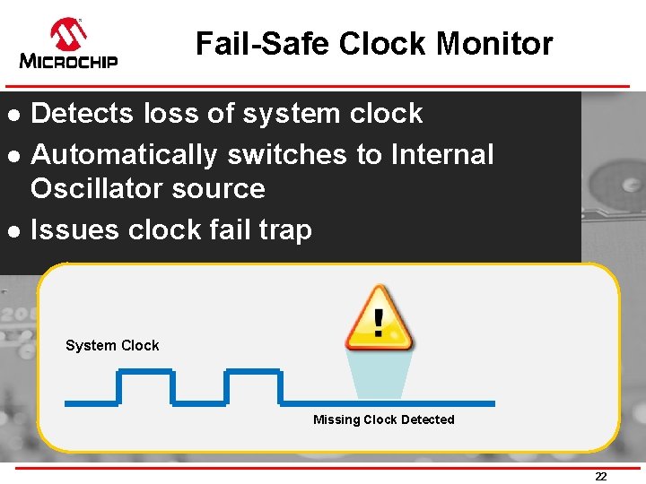
Fail-Safe Clock Monitor l l l Detects loss of system clock Automatically switches to Internal Oscillator source Issues clock fail trap System Clock Missing Clock Detected 22
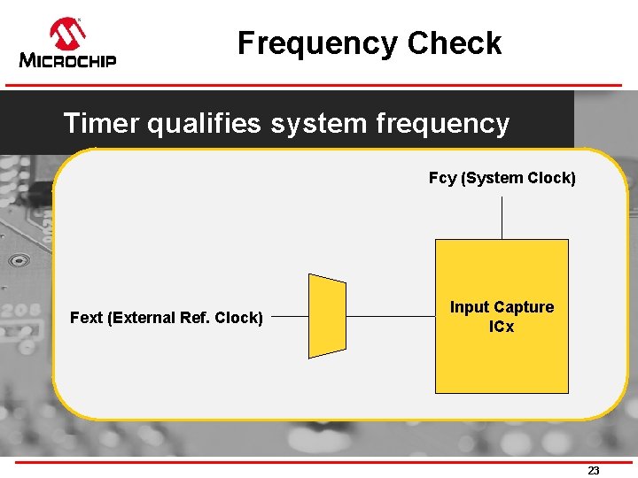
Frequency Check Timer qualifies system frequency Fcy (System Clock) Fext (External Ref. Clock) Input Capture ICx 23
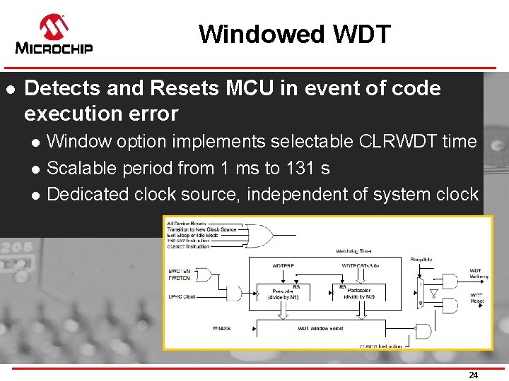
Windowed WDT l Detects and Resets MCU in event of code execution error l l l Window option implements selectable CLRWDT time Scalable period from 1 ms to 131 s Dedicated clock source, independent of system clock 24
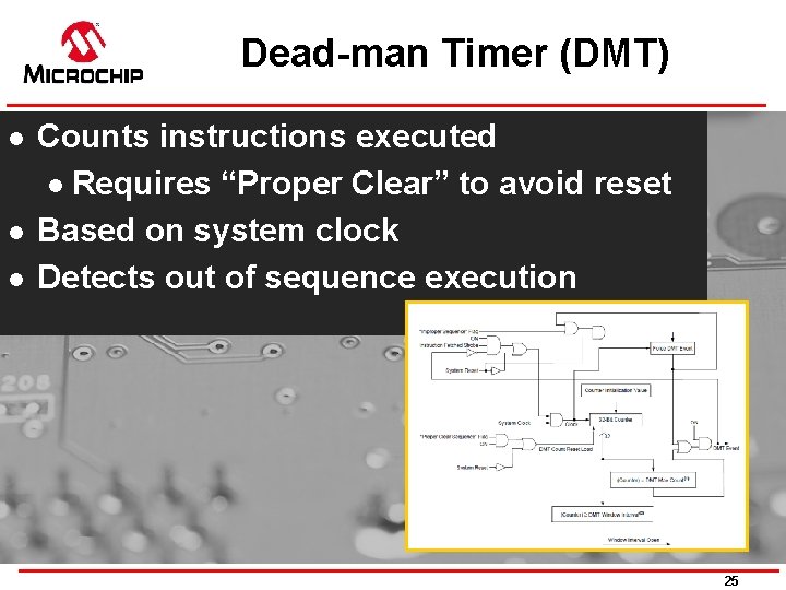
Dead-man Timer (DMT) l l l Counts instructions executed l Requires “Proper Clear” to avoid reset Based on system clock Detects out of sequence execution 25
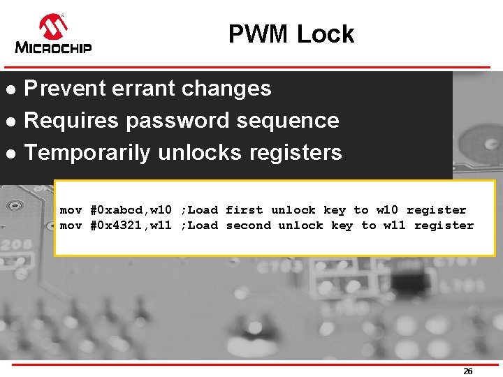
PWM Lock l l l Prevent errant changes Requires password sequence Temporarily unlocks registers mov #0 xabcd, w 10 ; Load first unlock key to w 10 register mov #0 x 4321, w 11 ; Load second unlock key to w 11 register 26
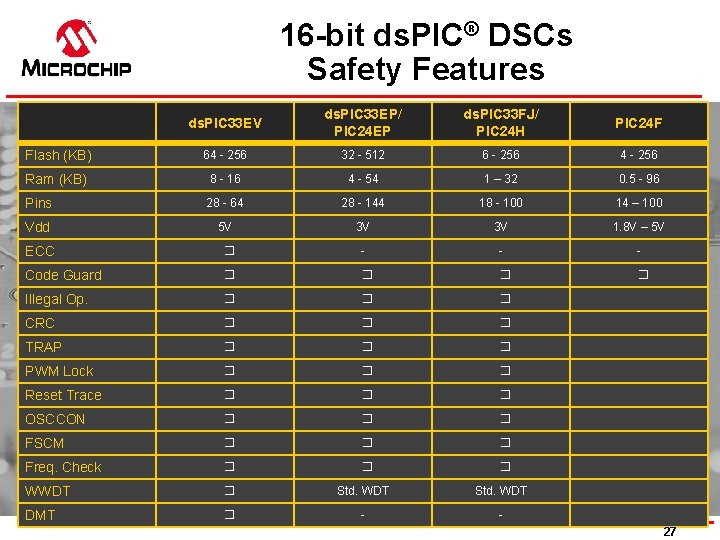
16 -bit ds. PIC® DSCs Safety Features ds. PIC 33 EV ds. PIC 33 EP/ PIC 24 EP ds. PIC 33 FJ/ PIC 24 H PIC 24 F Flash (KB) 64 - 256 32 - 512 6 - 256 4 - 256 Ram (KB) 8 - 16 4 - 54 1 – 32 0. 5 - 96 Pins 28 - 64 28 - 144 18 - 100 14 – 100 Vdd 5 V 3 V 3 V 1. 8 V – 5 V ECC � - - - Code Guard � � Illegal Op. � � � CRC � � � TRAP � � � PWM Lock � � � Reset Trace � � � OSCCON � � � FSCM � � � Freq. Check � � � WWDT � Std. WDT DMT � - 27
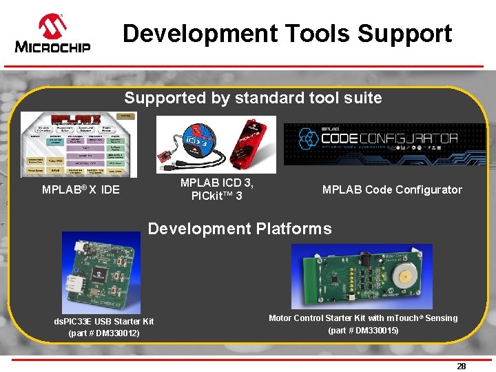
Development Tools Supported by standard tool suite MPLAB ICD 3, PICkit™ 3 MPLAB® X IDE MPLAB Code Configurator Development Platforms ds. PIC 33 E USB Starter Kit (part # DM 330012) Motor Control Starter Kit with m. Touch ® Sensing (part # DM 330015) 28

32 -bit MCU Safety Features
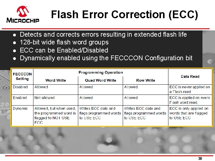
Flash Error Correction (ECC) l l Detects and corrects errors resulting in extended flash life 128 -bit wide flash word groups ECC can be Enabled/Disabled Dynamically enabled using the FECCCON Configuration bit 30
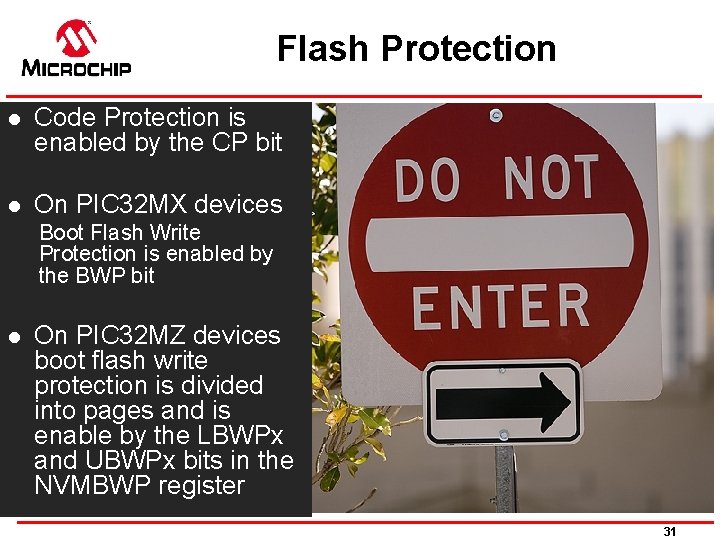
Flash Protection l Code Protection is enabled by the CP bit l On PIC 32 MX devices Boot Flash Write Protection is enabled by the BWP bit l On PIC 32 MZ devices boot flash write protection is divided into pages and is enable by the LBWPx and UBWPx bits in the NVMBWP register 31
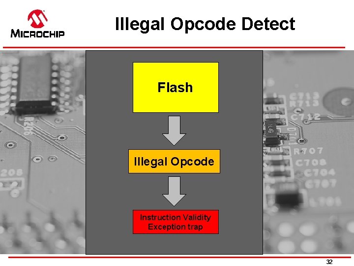
Illegal Opcode Detect Flash Illegal Opcode Instruction Validity Exception trap 32
32 -bit CRC Module 32 -bit Programmable CRC Generation module: CRC module can be assigned to any of the available DMA channels CRC module is highly configurable 33
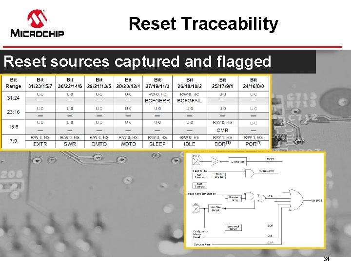
Reset Traceability Reset sources captured and flagged 34
OSCCON Lock Sequence Password sequence l l l Prevents errant frequency changes Requires two back to back writes Separate upper and lower byte writes l l Upper byte is oscillator source Lower byte is oscillator enable 35
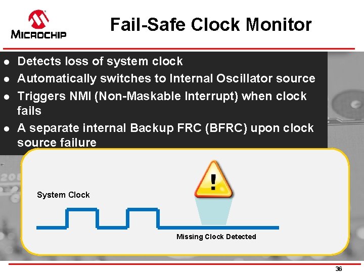
Fail-Safe Clock Monitor l l Detects loss of system clock Automatically switches to Internal Oscillator source Triggers NMI (Non-Maskable Interrupt) when clock fails A separate internal Backup FRC (BFRC) upon clock source failure System Clock Missing Clock Detected 36
High Voltage Detect (HVD) Monitors the core voltage at the VCAP pin I/O Pins disabled if voltage above the required level is detected on VCAP 37
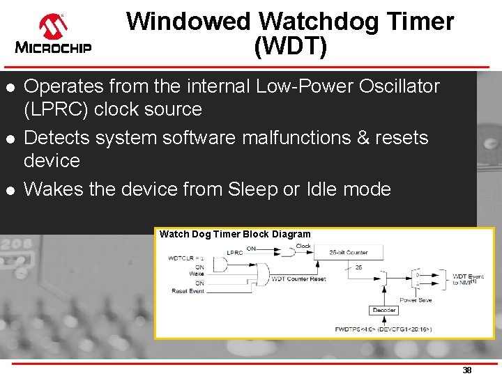
Windowed Watchdog Timer (WDT) l l l Operates from the internal Low-Power Oscillator (LPRC) clock source Detects system software malfunctions & resets device Wakes the device from Sleep or Idle mode Watch Dog Timer Block Diagram 38
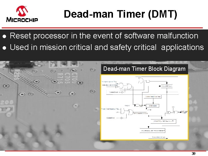
Dead-man Timer (DMT) l l Reset processor in the event of software malfunction Used in mission critical and safety critical applications Dead-man Timer Block Diagram 39
Misc. Lock Functions l Peripheral Module Disable Lock l l Memory Protect l l Disables a peripheral module by stopping all clock sources supplied Peripheral and memory region access control I/O (PPS) l Lock the I/O assignment for that pin 40
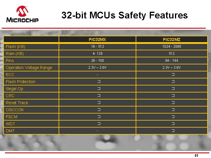
32 -bit MCUs Safety Features PIC 32 MX PIC 32 MZ Flash (KB) 16 - 512 1024 - 2048 Ram (KB) 4 - 128 512 28 - 100 64 - 144 2. 3 V – 3. 6 V Pins Operation Voltage Range ECC - � Flash Protection � � Illegal Op. � � CRC � � Reset Trace � � OSCCON � � FSCM � � WDT � � DMT - � 41
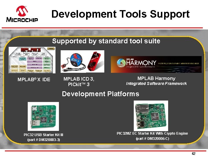
Development Tools Supported by standard tool suite MPLAB® X IDE MPLAB ICD 3, PICkit™ 3 MPLAB Harmony Integrated Software Framework Development Platforms PIC 32 USB Starter Kit III (part # DM 320003 -3) PIC 32 MZ EC Starter Kit With Crypto Engine (part # DM 320006 -C) 42

Certified Class B Library AN 1778 & AN 1799
Library Scope Class B Safety Software Library routines detect the occurrence of faults in a single channel CPU Developed in accordance with IEC 60730 to support Class B certification process Routines directly integrate into MCU applications to test and verify the critical functionalities without affecting the end application 44
Supported Architectures PIC 16 F 8 -bit MCU PIC 18 F 8 -bit MCU PIC 24 F 16 -bit MCU ds. PIC 33 E 16 -bit DSC PIC 32 32 -bit MCU Class B Library 45
Library Coverage CPU Registers Program Counter Interrupts Clock Frequency Memory Testing 46
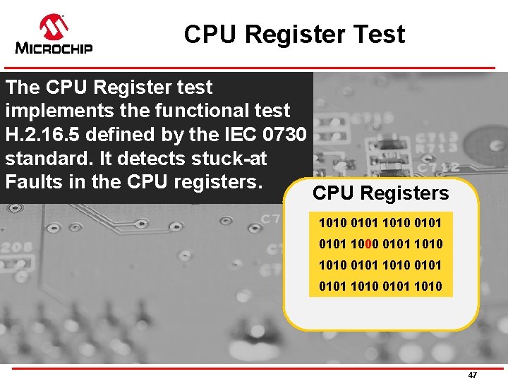
CPU Register Test The CPU Register test implements the functional test H. 2. 16. 5 defined by the IEC 0730 standard. It detects stuck-at Faults in the CPU registers. CPU Registers 1010 0101 1000 0101 1010 0101 1010 47
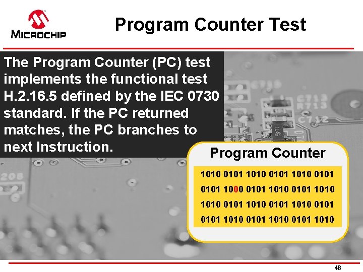
Program Counter Test The Program Counter (PC) test implements the functional test H. 2. 16. 5 defined by the IEC 0730 standard. If the PC returned matches, the PC branches to next Instruction. Program Counter 1010 0101 1000 0101 1010 0101 1010 0101 1010 48
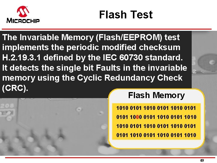
Flash Test The Invariable Memory (Flash/EEPROM) test implements the periodic modified checksum H. 2. 19. 3. 1 defined by the IEC 60730 standard. It detects the single bit Faults in the invariable memory using the Cyclic Redundancy Check (CRC). Flash Memory 1010 0101 1000 0101 1010 0101 1010 0101 1010 49
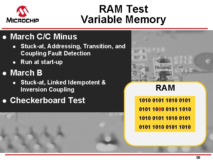
RAM Test Variable Memory l March C/C Minus l l l March B l l Stuck-at, Addressing, Transition, and Coupling Fault Detection Run at start-up Stuck-at, Linked Idempotent & Inversion Coupling Checkerboard Test RAM 1010 0101 1000 0101 1010 0101 1010 50
Interrupt Test The Interrupt test implements the independent time slot monitoring H. 2. 18. 10. 4 defined by the IEC 60730 standard. It checks whether the number of interrupts that occurred is within the predefined range. Interrupts Timer Generated Int. Line Freq. Generated 51
Oscillator Test Clock test implements the independent time slot monitoring H. 2. 18. 10. 4 defined by the IEC 60730 standard. It verifies the reliability of the system clock, i. e. too fast or too slow Oscillator Secondary Osc. Line Freq. Generated 52
Thanks! 53
- Slides: 53