Physics of Nuclear Medicine SPECT and PET Jerry


: measure of absorbed dose to whole body,")


 • • • 40 to 100 PM tubes (d = 5")


 is deposited in the")


 Computed Tomography) • Tomographic images can be")


 Calculate Projections (P’) Calculation Includes Attenuation Scatter Blur with depth")

 = I 0 e-mx • Assume uniform attenuation •")
 § Non-diagnostic CT § Diagnostic CT")
 – Positron decay characteristics – Coincidence and angular correlation –")


")
 with lots of little detectors (up to 23,")


 system like the gamma")


 2015 (Simultaneous acquisition) Nuclear Medicine Physics for Radiology")


- Slides: 53
Physics of Nuclear Medicine, SPECT and PET Jerry Allison, Ph. D. Department of Radiology Medical College of Georgia Augusta University
Outline • • • Radionuclides in Nuclear Medicine Radiation Dose Gamma Camera Basics SPECT (Single Photon Emission Computed Tomography) PET (Positron Emission Tomography
Radionuclides used in nuclear medicine Less than 20 radionuclides but hundreds of labeled compounds © Physics in Nuclear Medicine: Cherry, Sorenson and Phelps, 4 th edition, 2012 3
Effective dose of NM procedures 4
Dose Definition • Effective dose E (Sv): measure of absorbed dose to whole body, the product of equivalent dose and organ specific weighting factors § Whole body dose equivalent to the nonuniform dose delivered 5
How to obtain a NM image? • Administer radiopharmaceutical (a radionuclide labeled to a pharmaceutical) • The radiopharmaceutical concentrates in the desired locations • Nucleus of the radionuclide decays to emit photons (g , x-ray) • Detect the photons using a “gamma camera”
Gamma Camera Basics Pulse Height Analysis position analysis X Y Z co m p ut e r amplify & sum p re - a m p P M T d e t e ct o r d is p la y c o llim a t o r p a t ie n t
Photomultiplier tube (PMT) • • • 40 to 100 PM tubes (d = 5 cm) in a modern gamma camera photocathode directly coupled to detector or connected using plastic light guides ultrasensitive to magnetic fields
Why collimator? – image formation w/o collimator with collimator images image detector collimator sources Image of a point source is the whole detector. Image of a point source is a point.
Why collimator? – image formation • to establish geometric relationship between the source and image • The collimator has a major affect on gamma camera sensitivity (count rate) and spatial resolution parallel-hole collimator
Collimators • Most often used: parallel-hole collimator • For thyroid and heart: pin-hole collimator • For brain and heart: converging collimator 2015 Nuclear Medicine Physics for Radiology Residents Sameer Tipnis, Ph. D, DABR
Collimator Summary • Collimator must be matched to energy of radionuclide • Efficiency changes little with distance to source (patient) • Resolution falls off quickly with distance to source (patient)
Energy spectrum of detector Septal penetration & scatter: energy deposited in detector is between 0 and E 0. energy window photopeak: all energy of g photons (E 0) deposited in detector
Photopeak All the energy of a g photon (E 0) is deposited in the detector e. g. E 0 = 140 ke. V for Tc-99 m p. e c. s or 14
Septral penetration & scatter spectrum Some of the energy of a g photon (E 0) is deposited in the detector NOT USEFUL FOR IMAGING c. s 30 ke. V x-ray p. e 15
Modern Camera Design • Most cameras use rectangular heads • Most cameras are designed to do SPECT imaging • The dual head is the most common design
SPECT (Single Photon Emission Tomographic imaging (SPECT) Computed Tomography) • Tomographic images can be produced by acquiring conventional gamma camera projection data at several angles around the patient § Similar to CT
Sinogram © Physics in Nuclear Medicine: Cherry, Sorenson and Phelps
© Physics in Nuclear Medicine: Cherry, Sorenson and Phelps
Filtered Back Projection • Attenuates streaks by filtering the projections © Physics in Nuclear Medicine: Cherry, Sorenson and Phelps
Iterative Reconstruction • Quantitatively more accurate § Can model various corrections • • Collimator Scatter System geometry Detector resolution • Slow • Being used increasingly in SPECT
Assume Some Image (I) Calculate Projections (P’) Calculation Includes Attenuation Scatter Blur with depth Compare to Measured Projection (P) Use P’ & P to form corrections Form New Image (I’) Is I-I’< * Done
Data Collection • Image matrix is collected § 64 x 64 or 128 x 128 • Each image row makes a slice • Multiple slices can be added to reduce noise
Attenuation correction: Chang Method I(x) = I 0 e-mx • Assume uniform attenuation • m = linear attenuation coefficient of soft tissue (0. 15 per cm for Tc-99 m) • X is tissue thickness along projection from emission data
Attenuation correction: Transmission measurements • X-ray source (SPECT/CT) § Non-diagnostic CT § Diagnostic CT
PET (Positron Emission Tomography) – Positron decay characteristics – Coincidence and angular correlation – Time of flight – PET detector/scanner design – Data corrections
Positron is an Anti-particle • When a particle and antiparticle interact they annihilate § Both particles are destroyed § Two photons(Gammarays) are created § Two photons are emitted in ~opposite directions (± 0. 25 degrees for F-18) Gamma 1 + - Gamma 2
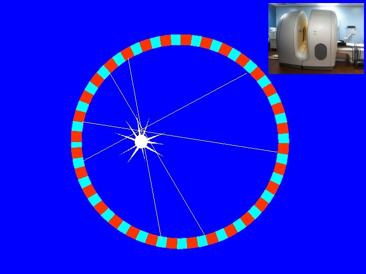
PET Imaging Concepts Where was the event? ? Coincidence
Where was the event?
Annihilation Detection In coincidence counting an event is ONLY registered if a signal is received from two detectors within a narrow window of time. A few nanoseconds is usually used. Coincidence
Time-of-Flight PET In “Time-of-Flight” pet, use of a very small time window (<100 picoseconds) can localize an annihilation event to within a few cm along the line of coincidence. Time-of-Flight PET can improve SNR. Coincidence
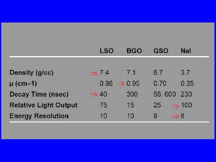
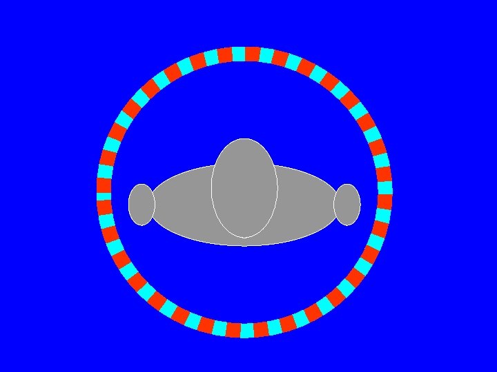
PET Scanner • Ring (multiple rings) with lots of little detectors (up to 23, 040) • Rings have axial coverage of up to 26 cm. • Detectors must have good stopping power • Detector must be fast for accurate coincidence measurements • Lutecium silicate LSO (LYSO) is commonly used (&BGO)
PET scanner • PET scanners lack conventional collimation so they have a high geometric efficiency • Some had septal rings to reduce cross talk from ring to ring § When rings in 2 D § When rings out 3 D Septa
Detector Needs • High Stopping Power § Much higher gamma ray energy (511 ke. V) • Light Output § Not as important because each gamma ray leaves a lot of energy in the crystal • Short Decay Time § Very important because of high count rate § Limits activity given to patient
Events in PET Scanners
Trues
Trues Rtrue = AO g 2 g. ACDe-m. T g. ACD~ h/2 D for ring(s) Where Rtrue = true coincidence rate Ao = Administered activity g = intrinsic efficiency g. ACD = geometric efficiency e-m. T = object attenuation h = detector thickness D = detector diameter
Scatter
Scatter-to-True Ratio • . 2 -. 5 brain • . 4 -2 body • Scatter (and Trues) are proportional to administered activity
Random RRnd = CTW Rtrue CTW = timing window
Random-to-True Ratio • . 1 – 2 brain • . 1 -1 body • Random-to-True Ratio high near high activity (Bladder)
Corrections • PET scanners use energy discrimination (pulse height analysis) system like the gamma camera to help eliminate scatter • Randoms are corrected for by measuring coincidence rates with a delay of time between 511 ke. V photon arrivals (so there are no trues).
Attenuation Correction • Like all radionuclide imaging there is a problem due to attenuation. • It is much less for PET than for Tc-99 m imaging • Correction is important for quantifying the metabolic activity of lesions (SUVs)
Attenuation Correction • CT data reconstructed to make a attenuation map of the body § Attenuation map information is used in image reconstruction
PET: CT Based Attenuation Correction © Nuclear medicine physics : a handbook for students and teachers, International Atomic Energy Agency, 2014
SPECT vs PET SPECT (Step-and-shoot acquisition) 2015 (Simultaneous acquisition) Nuclear Medicine Physics for Radiology Residents Sameer Tipnis, Ph. D, DABR
SPECT & PET • SPECT – 2 views from opposite sides § Res. ~ collimator res. , which degrades rapidly with increasing distance from collimator face • PET – Simultaneous acquisition § Res. ~ detector width; is max in center of ring • SPECT sensitivity ~ 0. 02% § Huge losses due to absorptive collimators • PET sensitivity- 2 D ~ 0. 2%; 3 D ~ 2% or higher § High sensitivity due to ACD (electronic collimation) § Allows higher frequency filters / higher spatial resolution 2015 Nuclear Medicine Physics for Radiology Residents Sameer Tipnis, Ph. D, DABR
• October 7, 2015 -- Researchers at the University of California, Davis (UC Davis) have received a five-year, $15. 5 million grant to develop what they are calling the world's first total-body PET scanner. § National Cancer Institute and will fund the Explorer project, led by Simon Cherry, Ph. D, distinguished professor of biomedical engineering and Ramsey Badawi, Ph. D, a professor of radiology. § The total-body PET scanner would image an entire body all at once, and it would acquire images much faster or at a much lower radiation dose by capturing almost all of the available signal from radiopharmaceuticals. … the design would line the entire inside of the PET camera bore with multiple rings of PET detectors. § … such a total-body PET design could reduce radiation dose by a factor of 40 or decrease scanning time from 20 minutes to 30 seconds http: //www. auntminnie. com/index. aspx? sec=s up&sub=mol&pag=dis&Item. ID=112051 51
References • Physics in Nuclear Medicine: Simon Cherry, James Sorenson and Michael Phelps, 4 th Edition, Elsevier, 2012 • International Atomic Energy Agency, SPECT/CT TECHNOLOGY & FACILITY DESIGN, https: //rpop. iaea. org/ • SPECT Single Photon Emission Computed Tomography, David S. Graff Ph. D, http: //www. slideshare. net/david. s. graff/spectpresentation • Quantitative capabilities of four state-of-the-art SPECT-CT cameras; Alain Seret, Daniel Nguyen and Claire Bernard, EJNMMI Research 2012, 2: 45 • Characterization of the count rate performance of modern gamma cameras, M. Silosky, V. Johnson, C. Beasley, and S. Cheenu Kappadath, Medical Physics 40, 032502 (2013) • Nuclear medicine physics : a handbook for students and teachers, International Atomic Energy Agency, 2014
References • Physics in Nuclear Medicine: Simon Cherry, James Sorenson and Michael Phelps, 4 th Edition, Elsevier, 2012 • Physics of PET-CT, David S. Graff Ph. D, http: //www. slideshare. net/david. s. graff/pet-ct-presentation • The Challenge of Detector Designs for PET, Thomas K. Lewellen, AJR: 195, August 2010 • Basics of PET Imaging; Physics, Chemistry, and Regulations, Gopal B. Saha, Springer, 2005