
Physics design on Injector1 RFQ OUYANG Huafu Contents





- Slides: 34
Physics design on Injector-1 RFQ OUYANG Huafu
Contents Ø RFQ R&D background at IHEP Ø C-ADS RFQ design philosophy Ø C-ADS RFQ dynamic design Ø C-ADS RFQ structure design Ø C-ADS RFQ water-cooling design and thermal analysis Ø Summary
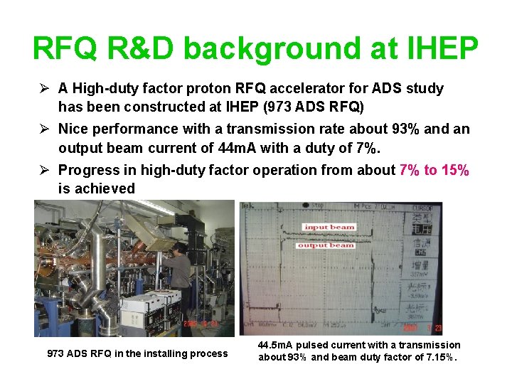
RFQ R&D background at IHEP Ø A High-duty factor proton RFQ accelerator for ADS study has been constructed at IHEP (973 ADS RFQ) Ø Nice performance with a transmission rate about 93% and an output beam current of 44 m. A with a duty of 7%. Ø Progress in high-duty factor operation from about 7% to 15% is achieved 973 ADS RFQ in the installing process 44. 5 m. A pulsed current with a transmission about 93% and beam duty factor of 7. 15%.
RFQ R&D background at IHEP Main parameters of 973 ADS RFQ Input Energy 75 ke. V Output Energy 3. 5 Me. V Peak Current 50 m. A Structure Type 4 -Vane RF Frequency 352. 2 MHz Inter-vane voltage 65 k. V Ø This 4. 75 long RFQ consists of two segments, which are resonantly coupled by a coupling cell. Each segment is formed by two technical modules. Maximum Surface E 33 MV/m (1. 8 Kilp) Structure Power 458[1. 4*PSuperfish (327 k. W)] Beam Power 175 k. W Total Power 638 k. W Total Length 4. 75 m One technical module (1. 2 m long)
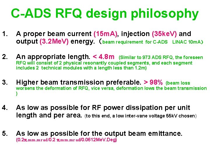
C-ADS RFQ design philosophy 1. A proper beam current (15 m. A), injection (35 ke. V) and output (3. 2 Me. V) energy. (beam requirement for C-ADS LINAC 10 m. A) 2. An appropriate length. < 4. 8 m 3. Higher beam transmission preferable. > 98% (beam loss 4. As low as possible for RF power dissipation per unit length and per area. (to this end, a low inter-vane voltage 55 k. V chosen) 5. As low as possible for the output beam emittance. (Similar to 973 ADS RFQ, the foreseen RFQ will consist of 2 physical resonantly coupled segments, and each segment includes 2 technical modules with a length less than 1. 2 m) worsens the deformation of RFQ, vice versa, deformation lows the beam transmission ) (0. 2. mm. mrad/0. 2 . mm. mrad/0. 0612 Me. V. Deg)
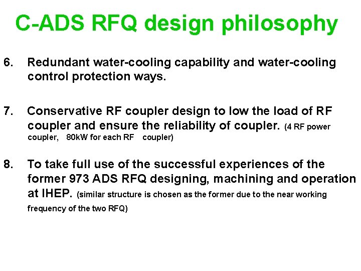
C-ADS RFQ design philosophy 6. Redundant water-cooling capability and water-cooling control protection ways. 7. Conservative RF coupler design to low the load of RF coupler and ensure the reliability of coupler. (4 RF power coupler, 80 k. W for each RF coupler) 8. To take full use of the successful experiences of the former 973 ADS RFQ designing, machining and operation at IHEP. (similar structure is chosen as the former due to the near working frequency of the two RFQ)
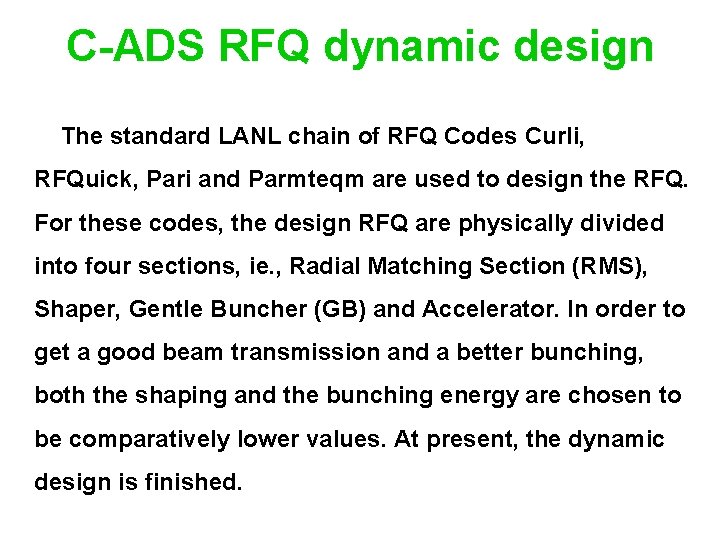
C-ADS RFQ dynamic design The standard LANL chain of RFQ Codes Curli, RFQuick, Pari and Parmteqm are used to design the RFQ. For these codes, the design RFQ are physically divided into four sections, ie. , Radial Matching Section (RMS), Shaper, Gentle Buncher (GB) and Accelerator. In order to get a good beam transmission and a better bunching, both the shaping and the bunching energy are chosen to be comparatively lower values. At present, the dynamic design is finished.
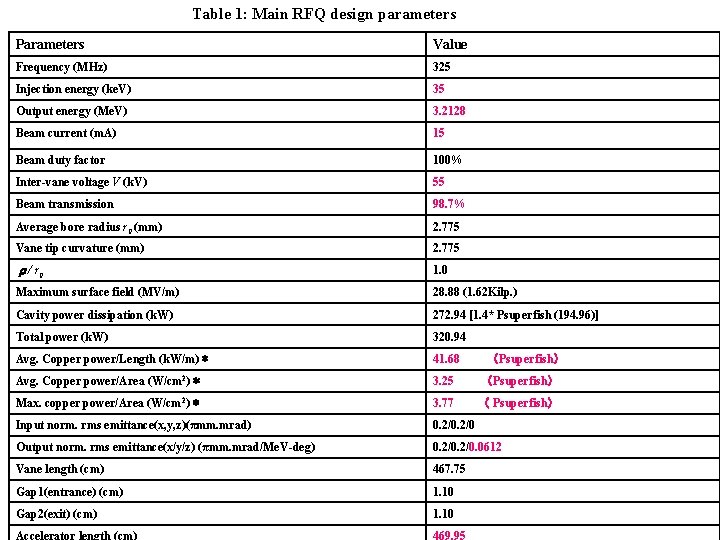
Table 1: Main RFQ design parameters Parameters Value Frequency (MHz) 325 Injection energy (ke. V) 35 Output energy (Me. V) 3. 2128 Beam current (m. A) 15 Beam duty factor 100% Inter-vane voltage V (k. V) 55 Beam transmission 98. 7% Average bore radius r 0 (mm) 2. 775 Vane tip curvature (mm) 2. 775 r / r 0 1. 0 Maximum surface field (MV/m) 28. 88 (1. 62 Kilp. ) Cavity power dissipation (k. W) 272. 94 [1. 4* Psuperfish (194. 96)] Total power (k. W) 320. 94 Avg. Copper power/Length (k. W/m)* 41. 68 (Psuperfish) Avg. Copper power/Area (W/cm 2)* 3. 25 (Psuperfish) Max. copper power/Area (W/cm 2)* 3. 77 ( Psuperfish) Input norm. rms emittance(x, y, z)(πmm. mrad) 0. 2/0 Output norm. rms emittance(x/y/z) (πmm. mrad/Me. V-deg) 0. 2/0. 0612 Vane length (cm) 467. 75 Gap 1(entrance) (cm) 1. 10 Gap 2(exit) (cm) 1. 10 Accelerator length (cm) 469. 95
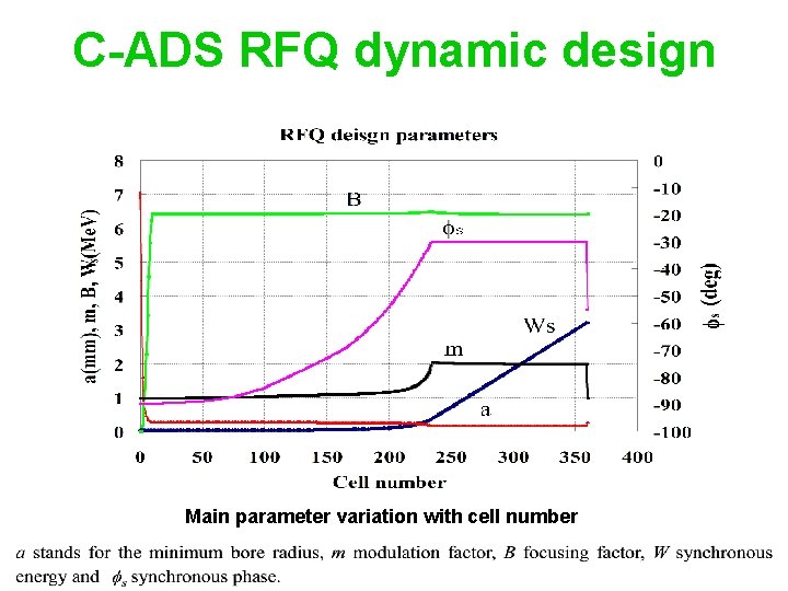
C-ADS RFQ dynamic design Main parameter variation with cell number
C-ADS RFQ dynamic design The beam transmission is about 98. 7%
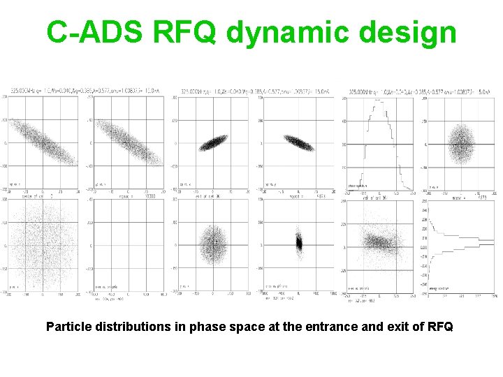
C-ADS RFQ dynamic design Particle distributions in phase space at the entrance and exit of RFQ
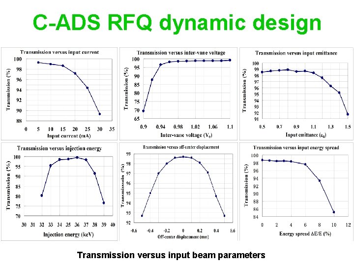
C-ADS RFQ dynamic design Transmission versus input beam parameters
C-ADS RFQ structure design RFQ consists of 2 physical resonantly coupled segments, and each segment includes 2 technical modules connected together with flanges. 4 four dipole rods are installed on the entrance plate, both sides of the coupling plate and the end plate. There are 64 plug tuners with a diameter of 55 mm and nominated penetration of 5. 2 mm into the cavity. 16 vacuum port bodies will be machined separately and then brazed together with RFQ cavity. There are 8 RF coupler ports and 4 ports will be used. At present, the structure design is basically finished. The mechanical length for the 4 modules (1) 1176. 558 mm (2) 1162. 329 mm (3) 1183. 657 mm (4) 1176. 928 mm. One quadrant of the RFQ 3 -dimension structure
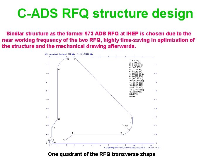
C-ADS RFQ structure design Similar structure as the former 973 ADS RFQ at IHEP is chosen due to the near working frequency of the two RFQ, highly time-saving in optimization of the structure and the mechanical drawing afterwards. One quadrant of the RFQ transverse shape
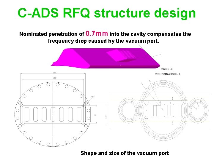
C-ADS RFQ structure design Nominated penetration of 0. 7 mm into the cavity compensates the frequency drop caused by the vacuum port. Shape and size of the vacuum port
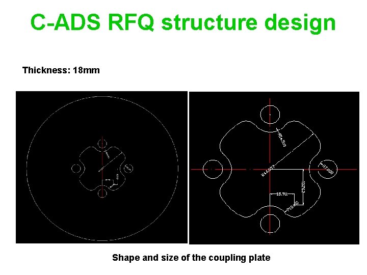
C-ADS RFQ structure design Thickness: 18 mm Shape and size of the coupling plate
C-ADS RFQ structure design Position: (31. 719,31. 719) Diameter: 15 mm Length: 169 mm Position, shape and size of the dipole stabilization rod
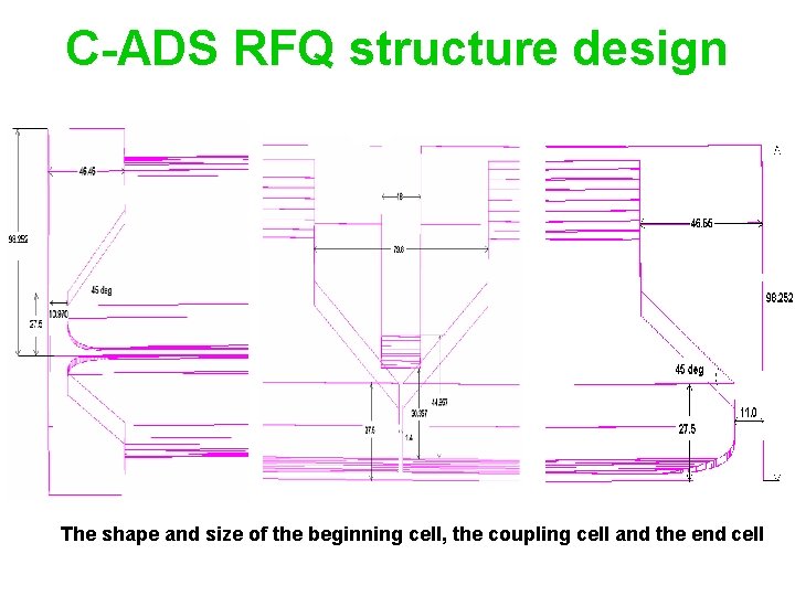
C-ADS RFQ structure design The shape and size of the beginning cell, the coupling cell and the end cell
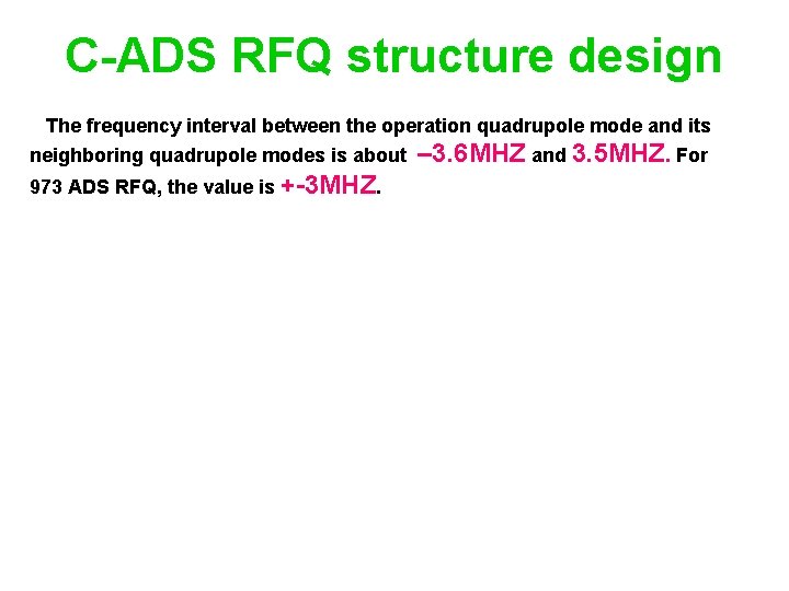
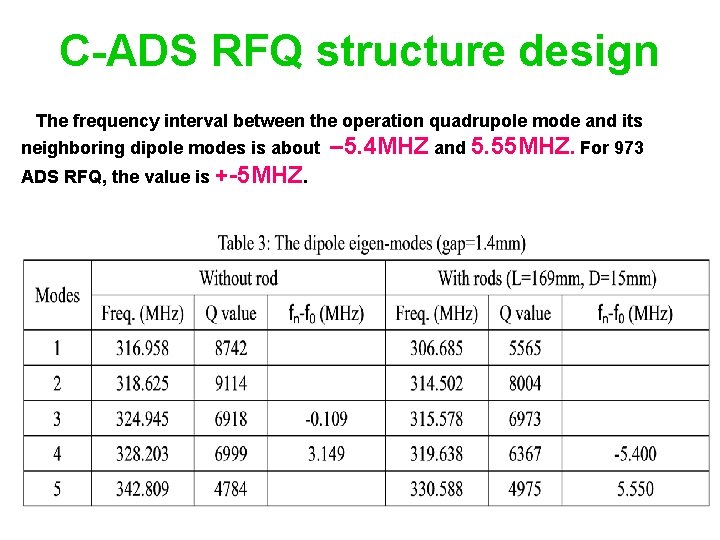
C-ADS RFQ structure design The frequency interval between the operation quadrupole mode and its neighboring quadrupole modes is about 973 ADS RFQ, the value is +-3 MHZ. – 3. 6 MHZ and 3. 5 MHZ. For
C-ADS RFQ structure design The frequency interval between the operation quadrupole mode and its neighboring dipole modes is about ADS RFQ, the value is +-5 MHZ. – 5. 4 MHZ and 5. 55 MHZ. For 973
C-ADS RFQ water-cooling design and thermal analysis Water-cooling serves two functions in an RFQ. One is to take away the power dissipated on the inside surface of the RFQ by the RF field to maintain thermal stability and to limit the deformation of RFQ. The other is to be used to tune the RFQ basically without effecting the field distribution profile when the RFQ is out of resonance, since the beam transmission of RFQ is very sensitive to the field profile, the ordinary frequency tuning method by the movable tuners is no more adopted in a RFQ operation.
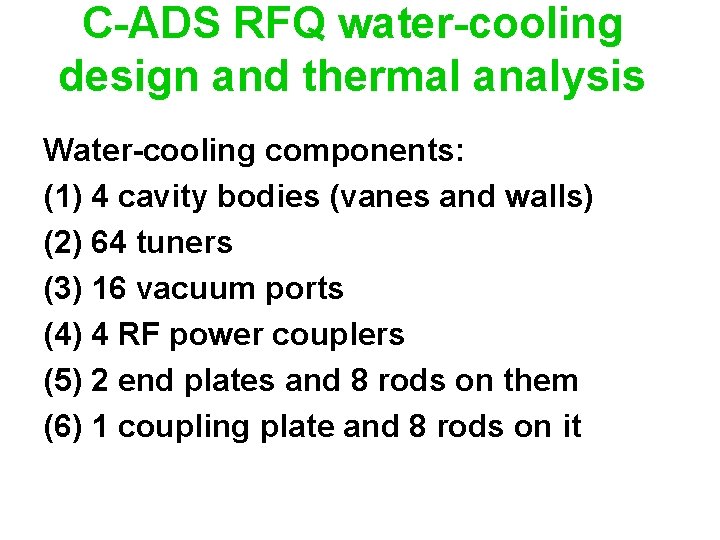
C-ADS RFQ water-cooling design and thermal analysis Water-cooling components: (1) 4 cavity bodies (vanes and walls) (2) 64 tuners (3) 16 vacuum ports (4) 4 RF power couplers (5) 2 end plates and 8 rods on them (6) 1 coupling plate and 8 rods on it
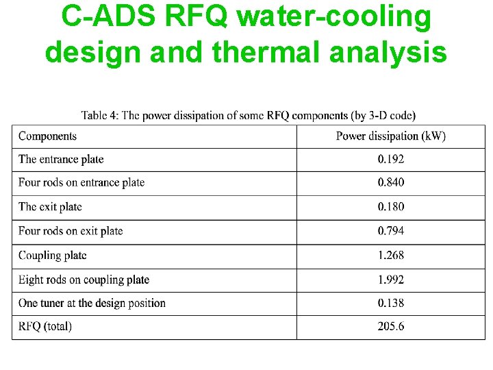
C-ADS RFQ water-cooling design and thermal analysis
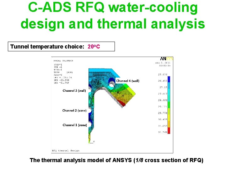
C-ADS RFQ water-cooling design and thermal analysis Tunnel temperature choice: 20 o. C The thermal analysis model of ANSYS (1/8 cross section of RFQ)
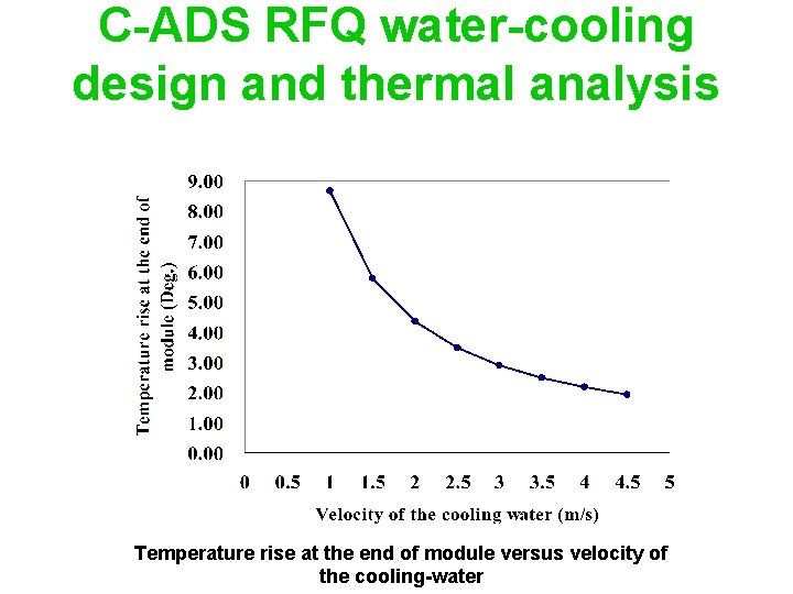
C-ADS RFQ water-cooling design and thermal analysis Temperature rise at the end of module versus velocity of the cooling-water
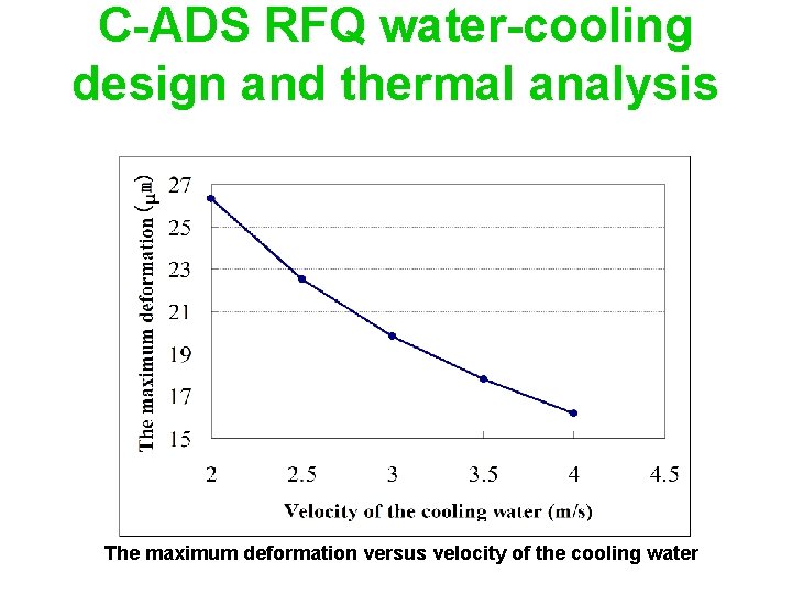
C-ADS RFQ water-cooling design and thermal analysis The maximum deformation versus velocity of the cooling water
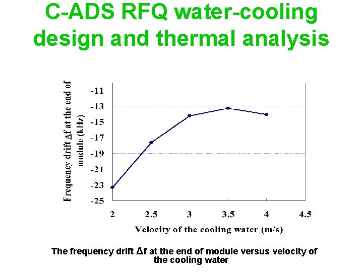
C-ADS RFQ water-cooling design and thermal analysis The frequency drift Δf at the end of module versus velocity of the cooling water
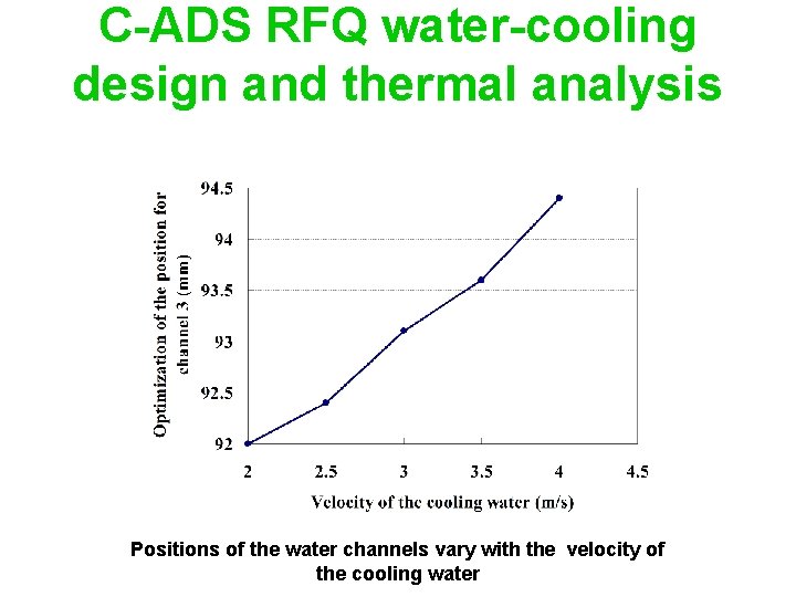
C-ADS RFQ water-cooling design and thermal analysis Positions of the water channels vary with the velocity of the cooling water
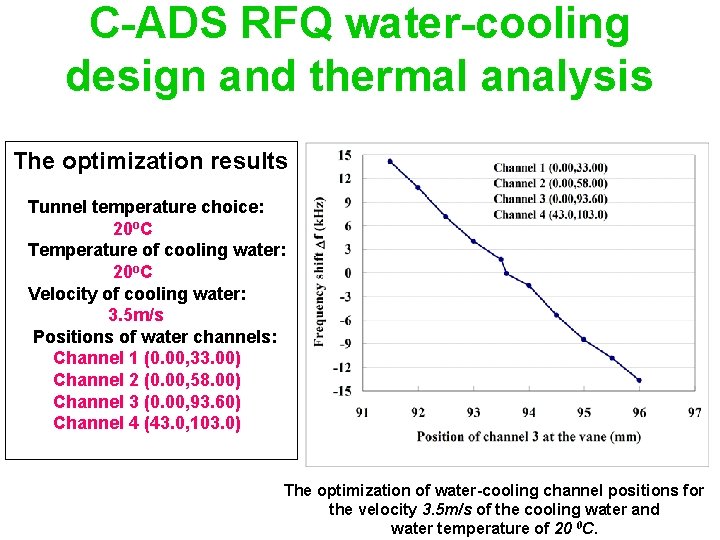
C-ADS RFQ water-cooling design and thermal analysis The optimization results Tunnel temperature choice: 20 o. C Temperature of cooling water: 20 o. C Velocity of cooling water: 3. 5 m/s Positions of water channels: Channel 1 (0. 00, 33. 00) Channel 2 (0. 00, 58. 00) Channel 3 (0. 00, 93. 60) Channel 4 (43. 0, 103. 0) The optimization of water-cooling channel positions for the velocity 3. 5 m/s of the cooling water and water temperature of 20 0 C.
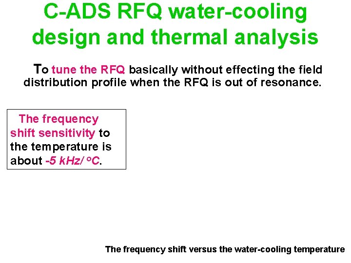
C-ADS RFQ water-cooling design and thermal analysis To tune the RFQ basically without effecting the field distribution profile when the RFQ is out of resonance. The frequency shift sensitivity to the temperature is about -5 k. Hz/ o. C. The frequency shift versus the water-cooling temperature
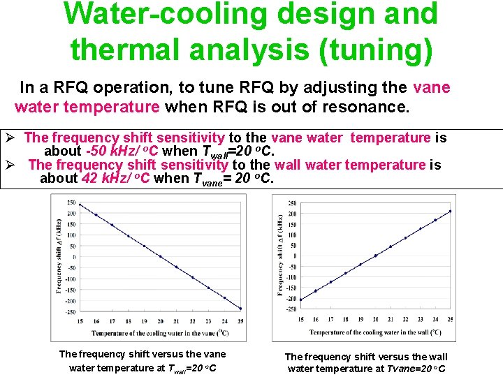
Water-cooling design and thermal analysis (tuning) In a RFQ operation, to tune RFQ by adjusting the vane water temperature when RFQ is out of resonance. Ø The frequency shift sensitivity to the vane water temperature is about -50 k. Hz/ o. C when Twall=20 o. C. Ø The frequency shift sensitivity to the wall water temperature is about 42 k. Hz/ o. C when Tvane= 20 o. C. The frequency shift versus the vane water temperature at Twall=20 o. C The frequency shift versus the wall water temperature at Tvane=20 o. C
Summary (1) A good dynamic design with high beam transmission, low power dissipation and low longitudinal emittance is got. (2) RFQ structure design proceeds well and rapidly due to much experience from the former 973 ADS RFQ built at IHEP. (3) Two dimension thermal analysis is used for the water -cooling design. Three dimension thermal analysis will be just used for checking the water-cooling design. (4) Mechanical design is being taken based on the present physical design.
THANK YOU!