
Physics 4 Inductance Prepared by Vince Zaccone For
Physics 4 Inductance Prepared by Vince Zaccone For Campus Learning Assistance Services at UCSB
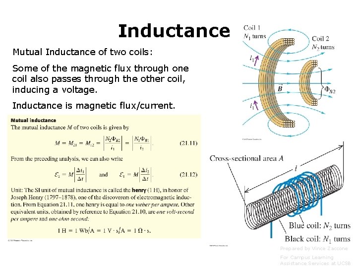
Inductance Mutual Inductance of two coils: Some of the magnetic flux through one coil also passes through the other coil, inducing a voltage. Inductance is magnetic flux/current. Prepared by Vince Zaccone For Campus Learning Assistance Services at UCSB
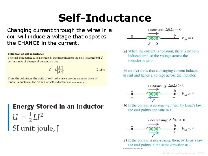
Self-Inductance Changing current through the wires in a coil will induce a voltage that opposes the CHANGE in the current. Prepared by Vince Zaccone For Campus Learning Assistance Services at UCSB
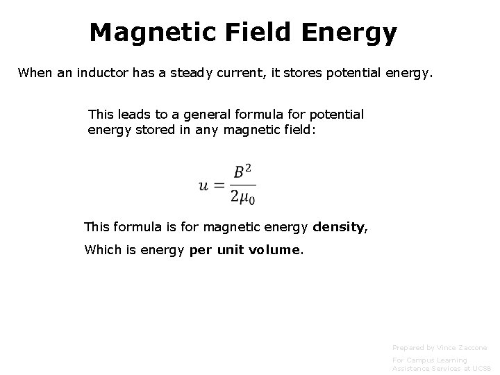
Magnetic Field Energy When an inductor has a steady current, it stores potential energy. This leads to a general formula for potential energy stored in any magnetic field: This formula is for magnetic energy density, Which is energy per unit volume. Prepared by Vince Zaccone For Campus Learning Assistance Services at UCSB
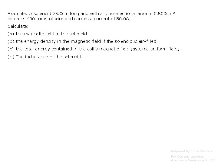
Example: A solenoid 25. 0 cm long and with a cross-sectional area of 0. 500 cm 2 contains 400 turns of wire and carries a current of 80. 0 A. Calculate: (a) the magnetic field in the solenoid. (b) the energy density in the magnetic field if the solenoid is air-filled. (c) the total energy contained in the coil’s magnetic field (assume uniform field). (d) The inductance of the solenoid. Prepared by Vince Zaccone For Campus Learning Assistance Services at UCSB
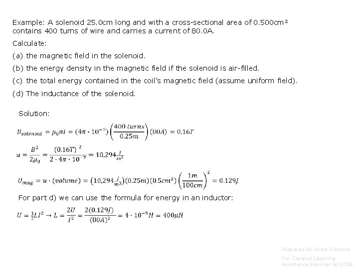
Example: A solenoid 25. 0 cm long and with a cross-sectional area of 0. 500 cm 2 contains 400 turns of wire and carries a current of 80. 0 A. Calculate: (a) the magnetic field in the solenoid. (b) the energy density in the magnetic field if the solenoid is air-filled. (c) the total energy contained in the coil’s magnetic field (assume uniform field). (d) The inductance of the solenoid. Solution: For part d) we can use the formula for energy in an inductor: Prepared by Vince Zaccone For Campus Learning Assistance Services at UCSB
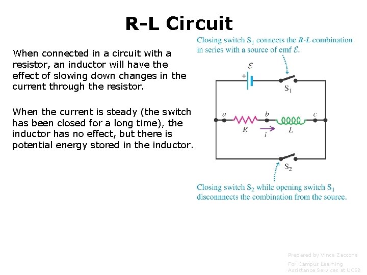
R-L Circuit When connected in a circuit with a resistor, an inductor will have the effect of slowing down changes in the current through the resistor. When the current is steady (the switch has been closed for a long time), the inductor has no effect, but there is potential energy stored in the inductor. Prepared by Vince Zaccone For Campus Learning Assistance Services at UCSB
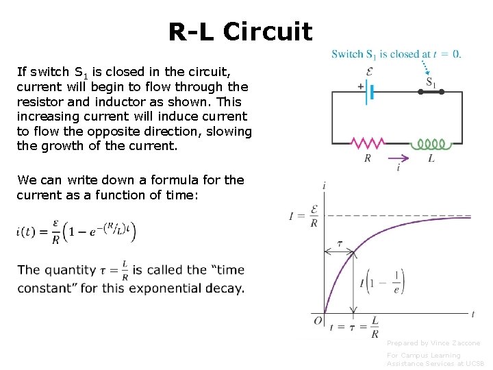
R-L Circuit If switch S 1 is closed in the circuit, current will begin to flow through the resistor and inductor as shown. This increasing current will induce current to flow the opposite direction, slowing the growth of the current. We can write down a formula for the current as a function of time: Prepared by Vince Zaccone For Campus Learning Assistance Services at UCSB
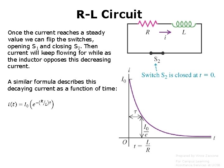
R-L Circuit Once the current reaches a steady value we can flip the switches, opening S 1 and closing S 2. Then current will keep flowing for while as the inductor opposes this decreasing current. A similar formula describes this decaying current as a function of time: Prepared by Vince Zaccone For Campus Learning Assistance Services at UCSB
Example: A 35. 0 V battery with negligible internal resistance, a 50. 0Ω resistor and a 1. 25 m. H inductor are connected in series with an open switch. The switch is suddenly closed. (a) How long after closing the switch will the current through the inductor reach half of its maximum value? (b) How long after closing the switch will the energy stored in the inductor reach half its maximum value? Prepared by Vince Zaccone For Campus Learning Assistance Services at UCSB
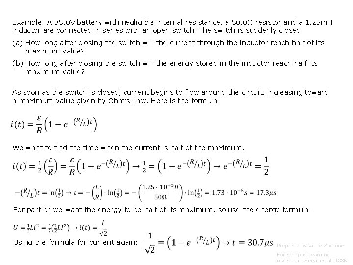
Example: A 35. 0 V battery with negligible internal resistance, a 50. 0Ω resistor and a 1. 25 m. H inductor are connected in series with an open switch. The switch is suddenly closed. (a) How long after closing the switch will the current through the inductor reach half of its maximum value? (b) How long after closing the switch will the energy stored in the inductor reach half its maximum value? As soon as the switch is closed, current begins to flow around the circuit, increasing toward a maximum value given by Ohm’s Law. Here is the formula: We want to find the time when the current is half of the maximum. For part b) we want the energy to be half of its maximum, so use the energy formula: Using the formula for current again: Prepared by Vince Zaccone For Campus Learning Assistance Services at UCSB
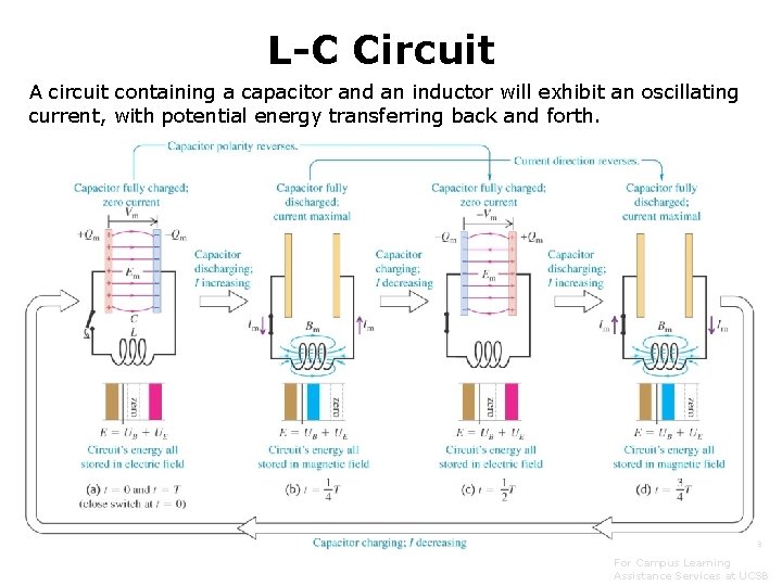
L-C Circuit A circuit containing a capacitor and an inductor will exhibit an oscillating current, with potential energy transferring back and forth. Prepared by Vince Zaccone For Campus Learning Assistance Services at UCSB
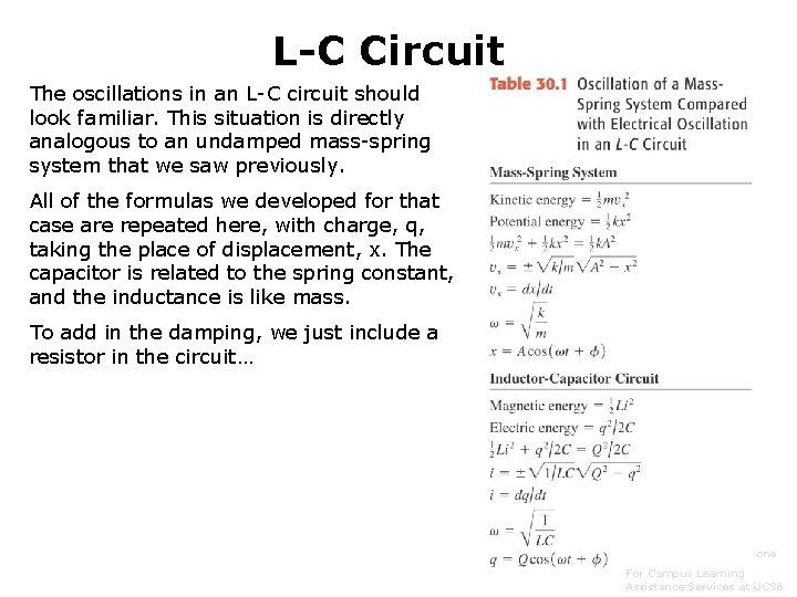
L-C Circuit The oscillations in an L-C circuit should look familiar. This situation is directly analogous to an undamped mass-spring system that we saw previously. All of the formulas we developed for that case are repeated here, with charge, q, taking the place of displacement, x. The capacitor is related to the spring constant, and the inductance is like mass. To add in the damping, we just include a resistor in the circuit… Prepared by Vince Zaccone For Campus Learning Assistance Services at UCSB
Example: In an L-C circuit, L=85. 0 m. H and C=3. 20μF. During the oscillations the maximum current in the inductor is 0. 850 m. A. (a) What is the maximum charge on the capacitor? (b) What is the magnitude of the charge on the capacitor at an instant when the current in the inductor has magnitude 0. 500 m. A? (c) How long does it take for the capacitor to go from maximum charge to zero charge? Prepared by Vince Zaccone For Campus Learning Assistance Services at UCSB
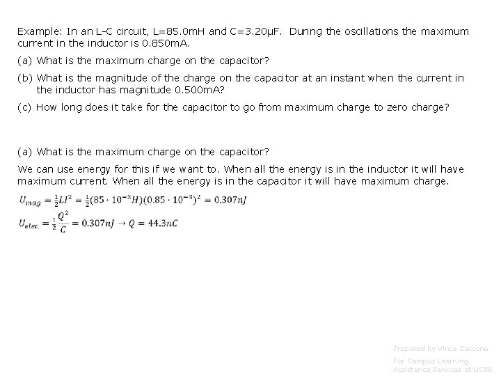
Example: In an L-C circuit, L=85. 0 m. H and C=3. 20μF. During the oscillations the maximum current in the inductor is 0. 850 m. A. (a) What is the maximum charge on the capacitor? (b) What is the magnitude of the charge on the capacitor at an instant when the current in the inductor has magnitude 0. 500 m. A? (c) How long does it take for the capacitor to go from maximum charge to zero charge? (a) What is the maximum charge on the capacitor? We can use energy for this if we want to. When all the energy is in the inductor it will have maximum current. When all the energy is in the capacitor it will have maximum charge. Prepared by Vince Zaccone For Campus Learning Assistance Services at UCSB
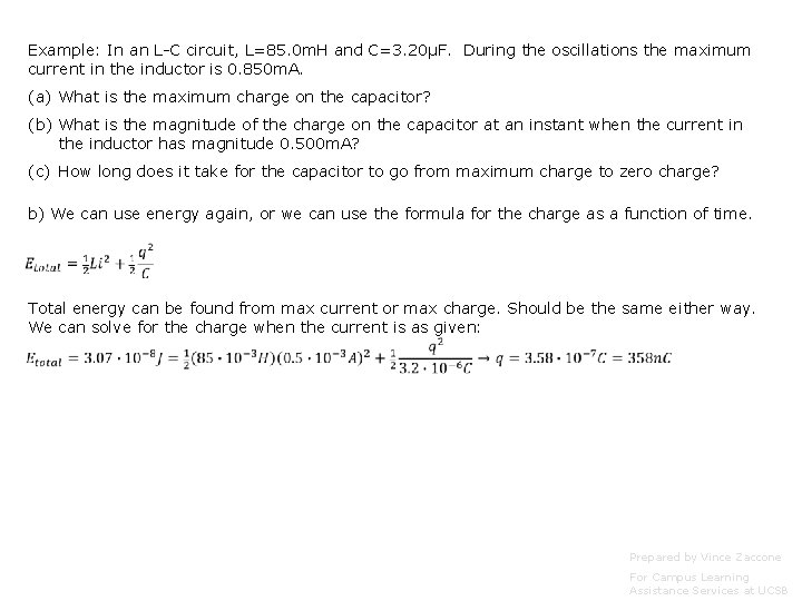
Example: In an L-C circuit, L=85. 0 m. H and C=3. 20μF. During the oscillations the maximum current in the inductor is 0. 850 m. A. (a) What is the maximum charge on the capacitor? (b) What is the magnitude of the charge on the capacitor at an instant when the current in the inductor has magnitude 0. 500 m. A? (c) How long does it take for the capacitor to go from maximum charge to zero charge? b) We can use energy again, or we can use the formula for the charge as a function of time. Total energy can be found from max current or max charge. Should be the same either way. We can solve for the charge when the current is as given: Prepared by Vince Zaccone For Campus Learning Assistance Services at UCSB

Example: In an L-C circuit, L=85. 0 m. H and C=3. 20μF. During the oscillations the maximum current in the inductor is 0. 850 m. A. (a) What is the maximum charge on the capacitor? (b) What is the magnitude of the charge on the capacitor at an instant when the current in the inductor has magnitude 0. 500 m. A? (c) How long does it take for the capacitor to go from maximum charge to zero charge? To go from no charge to fully charged is a quarter of a cycle, so we need to find the period of the oscillation. We have a formula for angular frequency: Rearrange this to get the period, then divide by 4: Prepared by Vince Zaccone For Campus Learning Assistance Services at UCSB
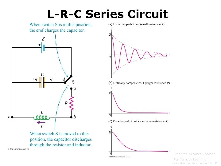
L-R-C Series Circuit Prepared by Vince Zaccone For Campus Learning Assistance Services at UCSB
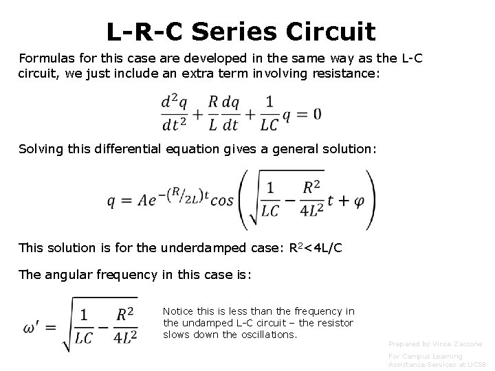
L-R-C Series Circuit Formulas for this case are developed in the same way as the L-C circuit, we just include an extra term involving resistance: Solving this differential equation gives a general solution: This solution is for the underdamped case: R 2<4 L/C The angular frequency in this case is: Notice this is less than the frequency in the undamped L-C circuit – the resistor slows down the oscillations. Prepared by Vince Zaccone For Campus Learning Assistance Services at UCSB
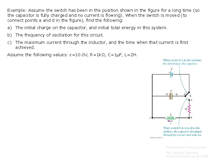
Example: Assume the switch has been in the position shown in the figure for a long time (so the capacitor is fully charged and no current is flowing). When the switch is moved (to connect points a and d in the figure), find the following: a) The initial charge on the capacitor, and initial total energy in this system. b) The frequency of oscillation for this circuit. c) The maximum current through the inductor, and the time when that current is first achieved. Assume the following values: ε=10. 0 V, R=1 kΩ, C=1μF, L=2 H. Prepared by Vince Zaccone For Campus Learning Assistance Services at UCSB
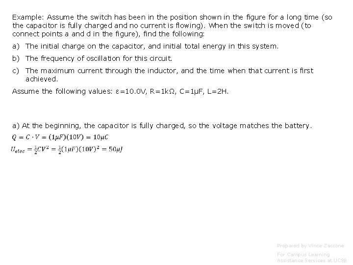
Example: Assume the switch has been in the position shown in the figure for a long time (so the capacitor is fully charged and no current is flowing). When the switch is moved (to connect points a and d in the figure), find the following: a) The initial charge on the capacitor, and initial total energy in this system. b) The frequency of oscillation for this circuit. c) The maximum current through the inductor, and the time when that current is first achieved. Assume the following values: ε=10. 0 V, R=1 kΩ, C=1μF, L=2 H. a) At the beginning, the capacitor is fully charged, so the voltage matches the battery. Prepared by Vince Zaccone For Campus Learning Assistance Services at UCSB
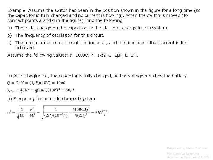
Example: Assume the switch has been in the position shown in the figure for a long time (so the capacitor is fully charged and no current is flowing). When the switch is moved (to connect points a and d in the figure), find the following: a) The initial charge on the capacitor, and initial total energy in this system. b) The frequency of oscillation for this circuit. c) The maximum current through the inductor, and the time when that current is first achieved. Assume the following values: ε=10. 0 V, R=1 kΩ, C=1μF, L=2 H. a) At the beginning, the capacitor is fully charged, so the voltage matches the battery. b) Frequency for an underdamped system: Prepared by Vince Zaccone For Campus Learning Assistance Services at UCSB
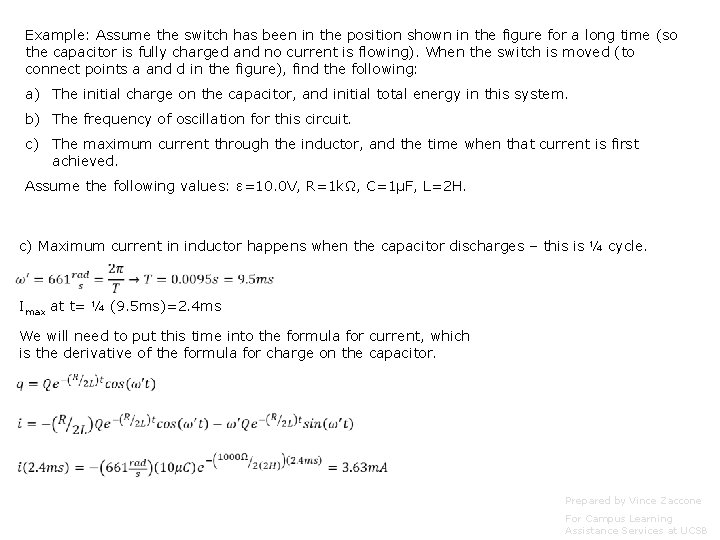
Example: Assume the switch has been in the position shown in the figure for a long time (so the capacitor is fully charged and no current is flowing). When the switch is moved (to connect points a and d in the figure), find the following: a) The initial charge on the capacitor, and initial total energy in this system. b) The frequency of oscillation for this circuit. c) The maximum current through the inductor, and the time when that current is first achieved. Assume the following values: ε=10. 0 V, R=1 kΩ, C=1μF, L=2 H. c) Maximum current in inductor happens when the capacitor discharges – this is ¼ cycle. Imax at t= ¼ (9. 5 ms)=2. 4 ms We will need to put this time into the formula for current, which is the derivative of the formula for charge on the capacitor. Prepared by Vince Zaccone For Campus Learning Assistance Services at UCSB
- Slides: 23