Physics 1202 Lecture 17 Todays Agenda Announcements Team


 to air")


 is used – in")


- Slides: 54
Physics 1202: Lecture 17 Today’s Agenda • Announcements: Team problems today – Team 10, 11 & 12: this Thursday • Homework #8: due Friday • Midterm 2: – Tuesday April 10 – Office hours if needed (M-2: 30 -3: 30 or TH 3: 00 -4: 00) • Chapter 26: – Geometrical Optics – Mirrors equation – Refraction
26 h R R-i h’ o-R o q q i
26 -1 The Reflection of Light • The law of reflection states that the angle of incidence equals the angle of reflection: © 2017 Pearson Education, Inc.
Flat Mirror Plane Mirror Virtual Image Object REAL q q o i o = -i VIRTUAL
Flat Mirror Images of Extended Objects Plane Mirror Virtual Image Extended Object h h’ o i o = -i REAL VIRTUAL Magnification: M = h’/ h = 1
26 -2 Applications of Plane Mirror • A corner reflector reflects light parallel to the incident ray, no matter the incident angle. • E. g. bicycle reflector © 2017 Pearson Education, Inc.
Image 6 Image 4 Image 2 6 4 2 180 o MIRROR 2 MIRROR 1 Multiple Reflection Object Image 3 Image 1 1 3 Image 5 5
26 -3 Spherical Mirrors • A spherical mirror has the shape of a section of a sphere. – If the outside is mirrored, it is convex – if the inside is mirrored, it is concave.
26 -3 Spherical Mirrors: definitions • Spherical mirrors have – a central axis (a radius of the sphere) and a – center of curvature (the center of the sphere) Concave mirror Convex mirror © 2017 Pearson Education, Inc.
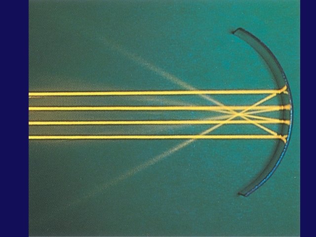
26 -3 Concave Spherical Mirrors • Consider parallel rays • They hit a spherical mirror • They come together at the focal point • This is a ray diagram for finding the focal point of a concave mirror.
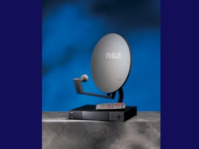
26 -3 Convex Spherical Mirrors • Consider parallel rays • They hit a spherical mirror • They appear to have come from the focal point, if the mirror is convex © 2017 Pearson Education, Inc.
26 -3 Spherical Mirrors • For a concave mirror, the focal length is postive, as the rays go through the focal point. • For a convex mirror, the focal length is negative, as the rays do not go through the focal point.
26 -3 Hyperbolic Mirrors • For spherical mirrors • Assumption that the rays do not hit the mirror very far from the principal axis • Otherwise, the image is blurred; – this is called spherical aberration, • Remedied by using a parabolic mirror instead. © 2017 Pearson Education, Inc.
26 -3 Spherical Mirrors • When the Hubble Space Telescope was first launched, its optics were marred by spherical aberration. This was fixed with corrective optics. © 2017 Pearson Education, Inc.
26 -4 Ray Tracing & Mirror Equation • We use three principal rays in finding the image produced by a concave mirror. – The parallel ray (P ray) reflects through the focal point. – The focal ray (F ray) reflects parallel to the axis. – The center-of-curvature ray (C ray) reflects back along its incoming path.
Concave Spherical Mirrors • We start by considering the reflections from a concave spherical mirror in the paraxial approximation (ie small angles of incidence close to a single axis): • First draw a ray (light blue) from the tip of the arrow through the center of the sphere. This ray is reflected straight back since the angle of incidence = 0. • Now draw a ray (white) from the tip of the arrow parallel to the axis. This ray is reflected with angle q as shown. q q R • Note that the two rays intersect in a point, suggesting an inverted image. • To check this, draw another ray (green) which comes in at some angle that is just right for the reflected ray to be parallel to the optical axis. • Note that this ray intersects the other two at the same point, as it must if an image of the arrow is to be formed there. • Note also that the green ray intersects the white ray at another point along the axis. We will call this point the focal point ( ).
The Mirror Equation • We will now transform the geometric drawings into algebraic equations: from triangles, R q eliminating , object h g b image i o Now we employ the small angle approximations: Plugging these back into the above equation relating the angles, we get: Defining the focal length f = R/2, This eqn is known as the mirror eqn. Note that there is no mention of q in this equation. Therefore, this eqn works for all q, ie we have an image!
Magnification • We have derived the mirror eqn which determines the image distance in terms of the object distance and the focal length: • What about the size of the image? h • How is h’ related to h? ? • From similar triangles: R h’ o Now, we can introduce a sign convention. We can indicate that this image is inverted if we define its magnification M as the negative number given by: q q i
26 -4 Mirror Equation: from the book • Derivation of mirror equation using the ray diagrams o o h R-i h h’ h’ o-R • equating i i
More Sign Conventions • Consider an object distance s which is less than the focal length: Ray Trace: • Ray through the center of the sphere (light blue) is reflected q straight back. R h q o • Ray parallel to axis (red) i passes through focal point f. f h’ • These rays diverge! ie these rays look they are coming from a point behind the mirror. • We call this a virtual image, meaning that no light from the object passes through the image point. • Proof left to student: This situation is described by the same mirror equations as long as we take the convention that images behind the mirror have negative image distances s’. ie: In this case, i < 0, which leads to M > 0, indicating that the image is virtual (i<0) and not inverted (M>0).
Concave-Planar-Convex • What happens as we change the curvature of the mirror? IMAGE: – Plane mirror: virtual » R=¥ upright (non-inverted) – Convex mirror: » R < 0 q q h h’ o i f IMAGE: virtual upright (non-inverted)
Lecture 17, ACT 1 • Let’s now consider a curved mirror. We start with CONVEX mirror. – Where do the rays which are reflected from the convex mirror shown intersect? (a) to left of (b) to right of (c) they don’t intersect
Lecture 17, ACT 2 • What is the nature of the image of the arrow? (a) Inverted and in front of the mirror (b) Inverted and in back of the mirror (c) Upright and in back of the mirror and, smaller !
Lecture 17, ACT 3 • In order for a real object to create a real, inverted enlarged image, a) we must use a concave mirror. b) we must use a convex mirror. c) neither a concave nor a convex mirror can produce this image.
Diagram: Concave Mirror, o > R • • The object is outside the center of curvature of the mirror The image is real The image is inverted The image is smaller than the object
Diagram: Concave Mirror, o < f • • The object is between the mirror and the focal point The image is virtual The image is upright The image is larger than the object
Diagram: Convex Mirror • • The object is in front of a convex mirror The image is virtual The image is upright The image is smaller than the object
Mirrors: image
Mirrors: conventions • Here are the sign conventions for concave and convex mirrors:
Mirror – Lens Definitions • Some important terminology we introduced last class, – o = distance from object to mirror (or lens) – i = distance from mirror to image o positive, i positive if on same side of mirror as o. – R = radius of curvature of spherical mirror – f = focal length, = R/2 for spherical mirrors. – Concave, Convex, and Spherical mirrors. – M = magnification, (size of image) / (size of object) negative means inverted image R q object h g b image o i
h i o 26. 5 f h’
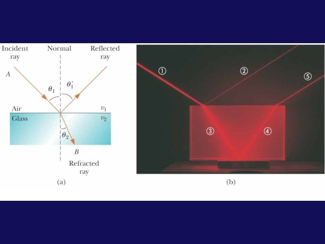
EM wave at an interface • What happens when light hits a surface of a material? • Three Possibilities – Reflected – Refracted (transmitted) – Absorbed incident ray reflected ray refracted ray MATERIAL 1 MATERIAL 2
25 -6: Index of Refraction • The wave incident on an interface can not only reflect, but it can also propagate into the second material. • Claim the speed of an electromagnetic wave is different in matter than it is in vacuum. – Recall, from Maxwell’s eqns in vacuum: – How are Maxwell’s eqns in matter different? · e 0 ® e , m 0 ® m (both increase) · Therefore, the speed of light in matter is smaller and related to the speed of light in vacuum by: where n = index of refraction of the material: · The index of refraction is frequency dependent: For example nblue > nred
Frequency Between Media • As light travels from one medium to another, its frequency does not change: v=ƒλ • Both the wave speed and the wavelength do change • The wavefronts do not pile up, nor are created or destroyed at the boundary, so ƒ must stay the same • The ratio of the indices of refraction of the two media can be expressed as various ratios λ 1 n 1 = λ 2 n 2
How does it work ? Mechanical analog
Refraction How is the angle of refraction related to the angle of incidence? – Unlike reflection, q 1 cannot equal q 2 !! 1 » n 1 ¹ n 2 Þ v 1 ¹ v 2 but, the frequencies (f 1, f 2) must be the same Þ the wavelengths must be different! Therefore, q 2 must be different from q 1 !! l • l 2 q 1 n 2 q 2
Snell’s Law l 1 • From the last slide: q 2 l 2 q 1 L q 2 q 1 q 2 The two triangles above each have hypotenuse L But, n 1 n 2
26 -5 The Refraction of Light • Here are some typical indices of refraction:
26 -5 The Refraction of Light • We can now write the angle of refraction in terms of the index of refraction: © 2017 Pearson Education, Inc.
26 -5 Refraction: Basic properties • Light may refract into a material where its speed is lower • angle of refraction is less than the angle of incidence – The ray bends toward the normal • Light may refract into a material where its speed is higher • angle of refraction is more than the angle of incidence – The ray bends away from the normal • If n 1 = n 2 Þ no effect • If light enters normal Þ no effect
Lecture 17, ACT 4 • Which of the following ray diagrams could represent the passage of light from air through glass and back to air? (a) (b) (c)
Optical effect • Refraction can make objects immersed in water appear broken • Refraction can create mirages
Lecture 17, ACT 5 • Which of the following ray diagrams could represent the passage of light from air through glass and back to air? (a) (b) (c) (d)
Total Internal Reflection – Consider light moving from glass (n 1=1. 5) to air (n 2=1. 0) n 1 n 2 incident ray q 1 qr q 2 refracted ray reflected ray GLASS AIR ie light is bent away from the normal. as q 1 gets bigger, q 2 gets bigger, but q 2 can never get bigger than 90° !! In general, if sin q 1 sin q. C (n 2 / n 1), we have NO refracted ray; we have TOTAL INTERNAL REFLECTION. For example, light in water which is incident on an air surface with angle q 1 > qc = sin-1(1. 0/1. 5) = 41. 8° will be totally reflected. This property is the basis for the optical fibers used in communication.
ACT 6: Critical Angle. . . An optical fiber is cladded by another dielectric. In case I this is water, with an index of refraction of 1. 33, while in case II this is air with an index of refraction of 1. 00. Compare the critical angles for total internal reflection in these two cases a) qc. I>qc. II b) qc. I=qc. II c) qc. I<qc. II water n =1. 33 Case I qc glass n =1. 5 water n =1. 33 air n =1. 00 Case II qc glass n =1. 5 air n =1. 00
ACT 7: Fiber Optics The same two fibers are used to transmit light from a laser in one room to an experiment Case I in another. Which makes a better fiber, the one in water (I) or the one in air (II) ? a) I Water b) II Air Case II water n =1. 33 qc glass n =1. 5 water n =1. 33 air n =1. 00 qc glass n =1. 5 air n =1. 00
26 -5 Applications of TIR • Total internal reflection (TIR) is used – in some binoculars – in optical fibers – In other optical devices © 2017 Pearson Education, Inc.
Internal Reflection in a Prism Submarine Periscopes to “see around corners”
Fiber Optics • An application of internal reflection • Plastic or glass rods are used to “pipe” light from one place to another • Applications include �medical use of fiber optic cables for diagnosis and correction of medical problems �Telecommunications
26 -5 Refraction & polarization • Brewster’s angle – special angle – light reflected is totally polarized • Reflected light is completely polarized – When angle between reflected and refracted beams is 90 o – Polarization is parallel to the reflecting surface • Applications – Remove reflection – Photographs of objects in water …
Recap of Today’s Topic : • Announcements: Team problems today – Team 10, 11 & 12: This Thursday • Homework #8: due Friday • Midterm 2: – Tuesday April 10 – Office hours if needed (M-2: 30 -3: 30 or TH 3: 00 -4: 00) • Chapter 26: – Geometrical Optics – Mirrors equation – Refraction