Physics 1202 Lecture 16 Todays Agenda Announcements Team

 x x z y")


 – Block electric field along their length")


 whose E")


- Slides: 54
Physics 1202: Lecture 16 Today’s Agenda • Announcements: Team problems today – Team 9: Garrett Schlegel, Joyce Nieh, Matthew Lombardo • Homework #7: due Monday • Midterm 1: – Average = 70% – Office hours if needed (M-2: 30 -3: 30 or TH 3: 00 -4: 00) • Chapter 25: – Power & pressure + Polarization • Chapter 26: – Geometrical Optics – Mirrors
Chap. 25 f( x ) x x z y
The EM Spectrum • Each wavelength shows different details
25 -4 Energy and Momentum in Electromagnetic Waves • The energy a wave delivers to a unit area in a unit time is called the intensity.
25 -4 Energy and Momentum in Electromagnetic Waves • Substituting for the energy density: • An electromagnetic wave also carries momentum:
Momentum in EM Waves • Electromagnetic waves contain momentum: • The momentum transferred to a surface depends on the area of the surface. Thus Pressure is a more useful quantity. • If a surface completely absorbs the incident light, the momentum gained by the surface p • We use the above expression plus Newton’s Second Law in the form F=Dp/Dt to derive the following expression for the Pressure, Þ • If the surface completely reflects the light, conservation of momentum indicates the light pressure will be double that for the surface that absorbs.
Radiation pressure • Therefore, it exerts pressure, called the radiation pressure: • Radiation pressure is responsible for the curvature of this comet’s dust tail.
25 -5: Polarization of light • Recall E&M wave y x 22_all_imgs_in_ppt z • This is an example of linearly polarized light – Electric field along a fixed axis ( here y ) • Most light source are nonpolarized – Electric field along random axis E
25 -5 Polarization • The polarization of an EM wave refers to the direction of its electric field • Polarized light has its electric fields all in the same direction. • Unpolarized light has its electric fields in random directions.
25 -5 Polarization • A beam of unpolarized light can be polarized by passing it through a polarizer • It allows only a particular component of the electric field to pass through • Here is a mechanical analog:
Polarizers • Made of long molecules (polymers) – Block electric field along their length – Electric field perpendicular passes through E E. H. Land (1909 – 1991): Polaroid E • So Eafter=E cosq • Recall that I ~ E 2 I = I 0 cos 2 q
25 -5 Law of Malus • Étienne-Louis Malus – 23 July 1775 – 24 February 1812 – French officer in Napoleon’army – Napoleon Egypt expedition: 1798 to 1801 • Since the intensity of light is proportional to the square of the field, the intensity of the transmitted beam is given by the Law of Malus: • The light exiting from a polarizer is polarized in the direction of the polarizer.
25 -5 Polarization • For unpolarized light passing through a polarizer – the transmitted intensity is half the initial intensity • A polarizer and an analyzer can be combined
25 -5 Polarization • Scattering of light by atoms/molecules – Unpolarized light can be partially or completely polarized – atoms/molecules which act as small antennas – If the light is already polarized, its transmission will depend on its polarization. © 2017 Pearson Education, Inc.
25 -5 Polarization • This means that sunlight will be polarized, depending on the angle our line of sight makes with the direction to the Sun.
25 -5 Polarization • Polarization can also occur when light reflects from a smooth surface:
26 h R R-i h’ o-R o q q i
26 -1 Reflection of Light • If a stone is dropped into a pond, circular waves emanate from the point where it landed. Rays, perpendicular to the wave fronts, give the direction in which the waves propagate. • As one moves farther from a point wave source, the wave fronts become more nearly flat. © 2017 Pearson Education, Inc.
Waves, Wavefronts, and Rays • Consider a light wave (not necessarily visible) whose E field is described by • This wave travels in 3 -D Representation the +x direction and RAYS Wave Fronts has no dependence on y or z, i. e. it is a plane wave.
Waves, Wavefronts, and Rays • For a point source: 3 -D Representation • This wave travels in the +r direction and has no dependence on angle, i. e. it is a spherical wave.
EM wave at an interface • What happens when light hits a surface of a material? • Three Possibilities – Reflected – Refracted (transmitted) – Absorbed incident ray reflected ray refracted ray MATERIAL 1 MATERIAL 2
26 -1 The Reflection of Light • The law of reflection states that the angle of incidence equals the angle of reflection: © 2017 Pearson Education, Inc.
Reflection • The angle of incidence equals the angle of reflection · qi = qr , where both angles are measured from the normal: · Note also, that all rays lie in the “plane of incidence” qi qr · Why? » This law is quite general; we supply a limited justification when surface is a good conductor, • Electric field lines are perpendicular to the conducting surface. • The components of E parallel to the surface of the incident and reflected wave must cancel!! Ei qi Er qr qi qr x
26 -1 Specular vs. diffuse reflection • Reflection from a smooth surface is called specular reflection; if the surface is rough, it is diffuse reflection. • What about forming an image ? • To answer this question – use law of reflection © 2017 Pearson Education, Inc.
26 -2 Images with a Plane Mirror • Light reflected from the flower and vase hits the mirror • Obeying the law of reflection, it enters the eye. • The eye interprets the ray as having had a straight-line path, and sees the image behind the mirror. • Properties of Images ‒ ‒ ‒ upright but appears reversed right to left. appears to be the same distance behind the mirror that the object is in front of the mirror. is the same size as the object.
Flat Mirror Plane Mirror Virtual Image Object REAL q q o i o = -i VIRTUAL
Flat Mirror Images of Extended Objects Plane Mirror Virtual Image Extended Object h h’ o i o = -i REAL VIRTUAL Magnification: M = h’/ h = 1
Plane Mirrors • Great for “magic” tricks • Your local friendly physicist …
26 -2 Applications of Plane Mirror • A corner reflector reflects light parallel to the incident ray, no matter the incident angle. • E. g. bicycle reflector © 2017 Pearson Education, Inc.
Image 6 Image 4 Image 2 6 4 2 180 o MIRROR 2 MIRROR 1 Multiple Reflection Object Image 3 Image 1 1 3 Image 5 5
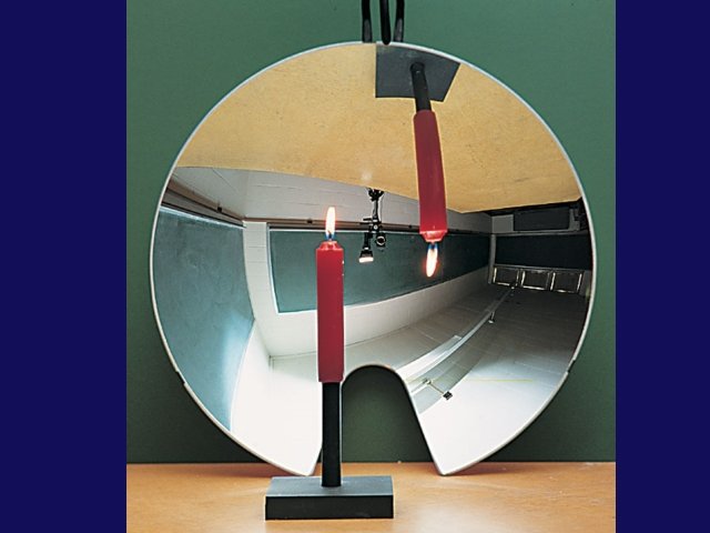
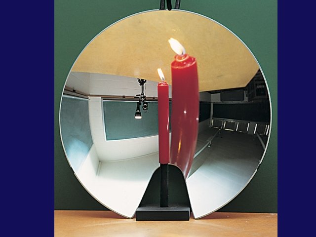
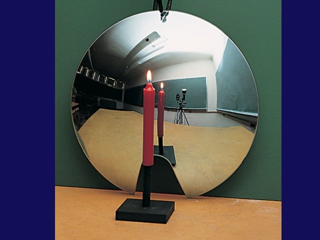
26 -3 Spherical Mirrors • A spherical mirror has the shape of a section of a sphere. – If the outside is mirrored, it is convex – if the inside is mirrored, it is concave.
26 -3 Spherical Mirrors: definitions • Spherical mirrors have – a central axis (a radius of the sphere) and a – center of curvature (the center of the sphere) Concave mirror Convex mirror © 2017 Pearson Education, Inc.
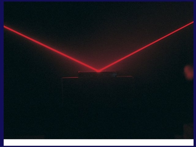
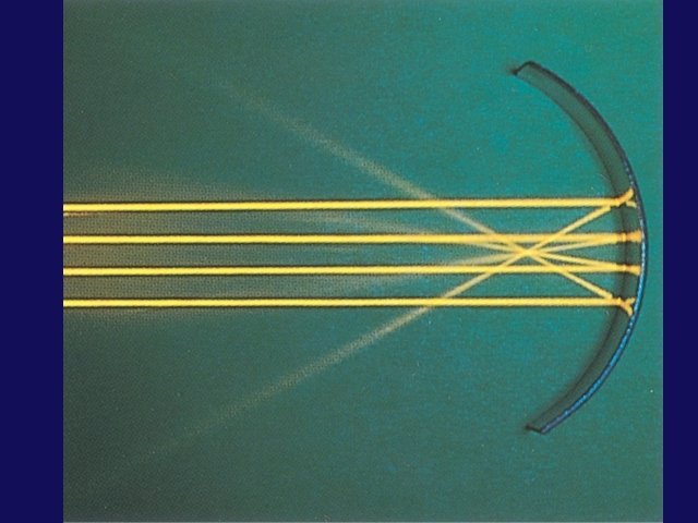
26 -3 Concave Spherical Mirrors • Consider parallel rays • They hit a spherical mirror • They come together at the focal point • This is a ray diagram for finding the focal point of a concave mirror.
26 -3 Convex Spherical Mirrors • Consider parallel rays • They hit a spherical mirror • They appear to have come from the focal point, if the mirror is convex © 2017 Pearson Education, Inc.
26 -3 Spherical Mirrors • For a concave mirror, the focal length is postive, as the rays go through the focal point. • For a convex mirror, the focal length is negative, as the rays do not go through the focal point.
26 -3 Hyperbolic Mirrors • For spherical mirrors • Assumption that the rays do not hit the mirror very far from the principal axis • Otherwise, the image is blurred; – this is called spherical aberration, • Remedied by using a parabolic mirror instead. © 2017 Pearson Education, Inc.
26 -3 Spherical Mirrors • When the Hubble Space Telescope was first launched, its optics were marred by spherical aberration. This was fixed with corrective optics. © 2017 Pearson Education, Inc.
26 -4 Ray Tracing & Mirror Equation • We use three principal rays in finding the image produced by a concave mirror. – The parallel ray (P ray) reflects through the focal point. – The focal ray (F ray) reflects parallel to the axis. – The center-of-curvature ray (C ray) reflects back along its incoming path.
Concave Spherical Mirrors • We start by considering the reflections from a concave spherical mirror in the paraxial approximation (ie small angles of incidence close to a single axis): • First draw a ray (light blue) from the tip of the arrow through the center of the sphere. This ray is reflected straight back since the angle of incidence = 0. • Now draw a ray (white) from the tip of the arrow parallel to the axis. This ray is reflected with angle q as shown. q q R • Note that the two rays intersect in a point, suggesting an inverted image. • To check this, draw another ray (green) which comes in at some angle that is just right for the reflected ray to be parallel to the optical axis. • Note that this ray intersects the other two at the same point, as it must if an image of the arrow is to be formed there. • Note also that the green ray intersects the white ray at another point along the axis. We will call this point the focal point ( ).
The Mirror Equation • We will now transform the geometric drawings into algebraic equations: from triangles, R eliminating , q object h g b image i o Now we employ the small angle approximations: Plugging these back into the above equation relating the angles, we get: Defining the focal length f = R/2, This eqn is known as the mirror eqn. Note that there is no mention of q in this equation. Therefore, this eqn works for all q, ie we have an image!
Magnification • We have derived the mirror eqn which determines the image distance in terms of the object distance and the focal length: • What about the size of the image? h • How is h’ related to h? ? • From similar triangles: R h’ o Now, we can introduce a sign convention. We can indicate that this image is inverted if we define its magnification M as the negative number given by: q q i
More Sign Conventions • Consider an object distance s which is less than the focal length: Ray Trace: • Ray through the center of the sphere (light blue) is reflected q straight back. R h q o • Ray parallel to axis (red) i passes through focal point f. f h’ • These rays diverge! ie these rays look they are coming from a point behind the mirror. • We call this a virtual image, meaning that no light from the object passes through the image point. • Proof left to student: This situation is described by the same mirror equations as long as we take the convention that images behind the mirror have negative image distances s’. ie: In this case, i < 0, which leads to M > 0, indicating that the image is virtual (i<0) and not inverted (M>0).
Concave-Planar-Convex • What happens as we change the curvature of the mirror? IMAGE: – Plane mirror: virtual » R=¥ upright (non-inverted) – Convex mirror: » R<0 q q h h’ o i f IMAGE: virtual upright (non-inverted)
Lecture 16, ACT 1 • Let’s now consider a curved mirror. We start with CONVEX mirror. – Where do the rays which are reflected from the convex mirror shown intersect? (a) to left of (b) to right of (c) they don’t intersect
Lecture 16, ACT 2 • What is the nature of the image of the arrow? (a) Inverted and in front of the mirror (b) Inverted and in back of the mirror (c) Upright and in back of the mirror
Lecture 16, ACT 3 • In order for a real object to create a real, inverted enlarged image, a) we must use a concave mirror. b) we must use a convex mirror. c) neither a concave nor a convex mirror can produce this image.
Mirror – Lens Definitions • Some important terminology we introduced last class, – o = distance from object to mirror (or lens) – i = distance from mirror to image o positive, i positive if on same side of mirror as o. – R = radius of curvature of spherical mirror – f = focal length, = R/2 for spherical mirrors. – Concave, Convex, and Spherical mirrors. – M = magnification, (size of image) / (size of object) negative means inverted image R q object h g b image o i
Recap of Today’s Topic : • Announcements: Team problems today – Team 9: Garrett Schlegel, Joyce Nieh, Matthew Lombardo • Homework #7: due Monday • Midterm 1: – Average = 70% – Office hours if needed (M-2: 30 -3: 30 or TH 3: 00 -4: 00) • Chapter 25: – Power & pressure + Polarization • Chapter 26: – Geometrical Optics – Mirrors