Physics 1202 Lecture 13 Todays Agenda Announcements NO


![Dimensions of capacitance • C = Q/V Þ [C] = F(arad) = C/V =](https://slidetodoc.com/presentation_image_h2/4e46a413378e2fdff3fd3223bf62da6a/image-12.jpg "Dimensions of capacitance • C = Q/V Þ [C] = F(arad) = C/V =")


![Step 5: Evaluate the answers • Are units OK ? – [ I ]](https://slidetodoc.com/presentation_image_h2/4e46a413378e2fdff3fd3223bf62da6a/image-26.jpg "Step 5: Evaluate the answers • Are units OK ? – [ I ]")


 As the conducting plate enters the field (position 1), the eddy currents are")


 • 2 coils wrapped")


 Vmax = Imax Z Þ f Imax R")


 + + - - C L C Þ Ý C L")
 • What do we need to do to turn our qualitative")


- Slides: 62
Physics 1202: Lecture 13 Today’s Agenda • Announcements: • NO HOMEWORK this week. • Review session • Team problems start this Thursday – Team 2: Analiese Bruder, Kristen Dean, Alison Smith – Team 3: Cameron Brodeur, Gavin Parker, Dylan Soares – Team 4: Joan Bosma, Joseph Forleo, Lee Martel – Team 5: Jonathan Aanensen, Thomas Buhl, Kelly Machado – Team 6: Aylin Aristizaba, Nancy Azhari, Zishan Li • Office hours: Monday 2: 30 -3: 30 Thursday 3: 00 -4: 00 • Midterm 1: Thursday March 1 st (in class) – Midterm sample + To-Know sheet on web already
Review: Chap. 19: Coulomb's Law q 1 q 2 r F 21 r F 12 q 1 q 2 1 F 12= r 4 pe 0 r 2 Þ 1 = k = 8. 987 109 N m 2/C 2 4 pe 0 SI Units: • r in meters • q in Coulombs • F in Newtons Charles Coulomb (1736 -1806) Introducing the Electric Field: 0
Electric field lines • The charge on the right is twice the magnitude of the charge on the left (and opposite in sign), so there are twice as many field lines, and they point toward the charge rather than away from negative: 16 lines → -2 q it. positive: 8 lines → +q
Gauss’s Law • Gauss’s law – electric flux through a closed surface is proportional to the charge enclosed by the surface:
Gauss’s Law • Useful to get electric field – By taking advantage of geometry • Charged plate – symmetry: E ⏊ to plate – uniformly charged: s = q/A – So E: constant magnitude
Gauss’s law E y • Charged line DE – symmetry: E ⏊ to line – uniformly charged: l = q/L r – So E: constant magnitude DE r' Dx ++++++++++++++++ x Dx E ⏊ to end r A=2 pr L L
20 -Electric Potential V Q 4 p 0 r Q 4 p 0 R R r R C R B r B q r A A path independence equipotentials
Electric potential V • By analogy with electric field • Therefore F ------------- Þ + • We have +++++++++++++ Þ
Point charges • For a point charge, the formula is: • For N charges �simply the algebraic sum of the potential due to each charge separately. Þ r 1 q 2 x r 2 r 3 q 3
Recall: Two infinite planes • Same charge but opposite • Fields of both planes cancel outside • They add up inside +++++++++++++ ------------- Perfect to store energy !
Example: Parallel Plate Capacitor • Calculate the capacitance: Assume +Q, -Q on plates with potential difference V. d A ++++ ----- Þ • As hoped for, the capacitance of this capacitor depends only on its geometry (A, d).
Dimensions of capacitance • C = Q/V Þ [C] = F(arad) = C/V = [Q/V] • A Farad is very large – Often will see µF or p. F A ++++ d ----- • Example: Two plates, A = 10 cm x 10 cm d = 1 cm apart Þ C = Ae 0/d = = 0. 01 m 2/0. 01 m * 8. 852 e-12 C 2/Jm = 8. 852 X 10 -12 F = 8. 852 p. F
R I 21 -1: Electric current I = DQ / Dt =RI
21 -2: Resistance & Ohm’s Law • Resistance is defined to be the ratio of the applied voltage to the current passing through. I R I V UNIT: OHM = • What does it mean ? it is the a measure of the friction slowing the motion of charges • Analogy with fluids
21 -3: Energy & Power Batteries & Resistors Energy expended chemical to electrical to heat Rate is: What’s happening? Assert: Energy “drop” per charge For Resistors: Units: Charges per time
R I =RI
Summary R 1 • Resistors in series – the current is the same in both R 1 and R 2 – the voltage drops add V R 2 • Resistors in parallel – the voltage drop is the same in both R 1 and R 2 – the currents add V R 1 R 2
1 R I 1 I 2 I 3 R 2 R 3
Capacitors in Parallel a a V Q 1 Q 2 º b Q V b Þ C = C 1 + C 2 Capacitors in Series a +Q -Q b º a +Q Þ -Q b
Example: Power in Resistive Electric Circuits A circuit consists of a 12 V battery with internal resistance of 2 connected to a resistance of 10 . The current in the resistor is I, and the voltage across it is V. The voltmeter and the ammeter can be considered ideal; that is, their resistances are infinity and zero, respectively. What is the current I and voltage V measured by those two instruments ? What is the power dissipated by the battery ? By the resistance ? What is the total power dissipated in the circuit ? Comment on these various powers.
Step 1: Focus on the problem • Drawing with relevant parameters – Voltmeter can be put a two places • What is the question ? – – – What is I ? What is V ? What is Pbattery ? What is PR ? What is Ptotal ? Comment on the various P’s V I I R V r 2 12 V 10 A
Step 2: describe the physics • What concepts are relevant ? – Potential difference in a loop is zero – Energy is dissipated by resistance • What are the known and unknown quantities ? – Known: R = 10 , r = 2 = 12 V – Unknown: I, V, P’s
Step 3: plan the solution • What are the relevant physics equations ? • Kirchoff’s first law: • Power dissipated: For a resistance
Step 4: solve with symbols • Find I: - Ir - IR = 0 I I R • Find V: r • Find the P’s: A
Step 4: solve numerically • Putting in the numbers
Step 5: Evaluate the answers • Are units OK ? – [ I ] = Amperes – [ V ] = Volts – [ P ] = Watts • Do they make sense ? – the values are not too big, not too small … – total power is larger than power dissipated in R » Normal: battery is not ideal: it dissipates energy
RC Circuits • Case 1: Charging a R b Q 1 = 0, Q 2 = Q and t 1 = 0, t 2 = t V C c • To get Current, I = d. Q/dt I Q t t
RC Circuits a • Case 2: Discharging: Q 1 = Q 0 , Q 2 = Q and t 1 = 0, t 2 = t • To discharge the capacitor we have to take the battery out of the circuit (V=0) R b V C c c • To get Current, I = d. Q/dt I Q t t
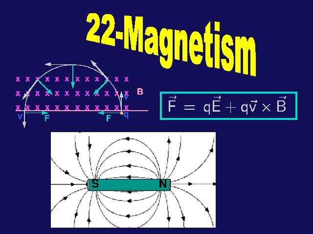
22 -2: Forces due to Magnetic Fields • Magnets exert forces on other magnets. • Also, B provides a force to a charged particle, but this force is in a direction perpendicular to the direction of the magnetic field. Right Hand Rule:
Circular motion • Force is perp. to v • q = 90 o so sinq = 1 or F=qv. B • Work proportional to cos f (recall 1201) ⎼ f : angle between F and Dx – cos f =0 (perpendicular) • W=0 Þ DK=0 – Kinetic energy not changed – Velocity constant: UCM ! R
The Hall Effect l Force balance c B I F - d vd c q. EH B I Hall voltage generated across the conductor a Using the relation between drift velocity and current we can write:
22 -5: Fmag on a Current Loop • Consider loop in magnetic field as on right: If field is ^ to plane of loop, the net force on loop is 0! – Force on top path cancels force on bottom path (F = IBL) x x Fx x x x – Force on right path cancels force on left path. (F = IBL) • If plane of loop is not ^ to field, there will be a non-zero torque on the loop! F x x x x x ix F x x x B x x F x B x F F.
Calculation of Torque • Suppose a square wire loop has width w (the side we see) and length L (into the screen). The torque is given by: B q x w F Þ F. q m Þ r rx. F q since: A = w. L = area of loop F • We can define the magnetic dipole moment of a current loop as follows: magnitude: m = A I Þ • Note: if loop consists of N turns, m = N A I
22 -6 Ampère’s Law for straight wire • Use Ampère’s law to find the magnetic field around a long, straight wire • B always parallel to circle • Constant magnitude on circle André-Marie Ampère Þ Born: Jan. 20, 1775 Lyon, France Died: June 10, 1836 Marseille, France
Toroid • Toroid defined by N total turns with current i. • B=0 outside toroid! • B inside the toroid • Ampere’s law ( I=Ni ) Þ • • xx x x xx • • • x x r xx xx • B • •
Faraday's Law n B B N S v S N B v q B
23 -5: Work & energy • Suppose we pull with velocity v a coil of resistance R through a region of constant magnetic field B. – What will be the induced current? » What direction? • Lenz’ Law Þ clockwise!! – What is the magnitude? » Magnetic Flux: xxxxxx x » Faraday’s Law: Þ I w v
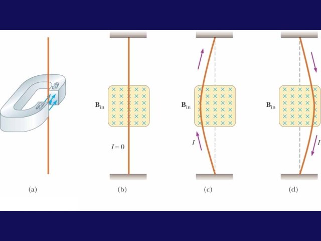
(a) As the conducting plate enters the field (position 1), the eddy currents are counterclockwise. As the plate leaves the field (position 2), the currents are clockwise. In either case, the force on the plate is opposite to the velocity, and eventually the plate comes to rest. (b) When slots are cut in the conducting plate, the eddy currents are reduced and the plate swings more freely through the magnetic field.
Inductance • The magnetic field produced by the current in the loop shown is proportional to that current. • The flux, therefore, is also proportional to the current. • We define this constant of proportionality between flux and current to be the inductance L. • We can also define the inductance L, using Faraday's Law, in terms of the emf induced by a changing current. I
23 -7: Inductance • The magnetic field produced by the current in the loop shown is proportional to that current. • The flux, therefore, is also proportional to the current. So, the inductance is I
Inductors in series & parallel L 1 • Like resistors: basically wires … • Inductors in series – the current is the same in both L 1 and L 2 – the voltage drops add V L 2 • Inductors in parallel – the voltage drop is the same in both L 1 and L 2 – the currents add V L 1 L 2
23 -10: Transformers • Device to change (or the voltage) • 2 coils wrapped around iron core • Primary (P) and secondary (S) • B-field inside core • Time varying current in P (with NP) • Faraday's Law: DF B = e P - NP Dt • Time varying flux induces emf in secondary coil S (with N S) DF B e S = - NS Dt • Same varying flux Þ
R C e ~ L w
Phasors • R: V in phase with i Þ • C: V lags i by 90° Þ • L: V leads i by 90° Þ • A phasor is a vector whose magnitude is the maximum value of a quantity (eg V or I) and which rotates counterclockwise in a 2 -d plane with angular velocity w. Recall uniform circular motion: The projections of r (on the vertical y axis) execute sinusoidal oscillation. y y w x
Suppose: Phasors for L, C, R i ß i w 0 wt i 0 w wt i 0 i i wt w
w - dependence in AC Circuits • The maximum current & voltage are related via the impedence Z • Currents AC-circuits as a function of frequency:
24 -5 RLC Circuits • Phasor diagram – useful to analyze an RLC circuit • Follow the loop • Total V V= VR + VL+ VC = Z Imax – VR = R Imax (in phase) – VL= XL Imax (leads by 90 o) – VC= XC Imax (lags by 90 o)
Phasors: LCR Imax (XL-XC) Vmax = Imax Z Þ f Imax R
24 -5 RLC Circuits • The phase angle for an RLC circuit is: • If XL = XC, the phase angle is zero, and the voltage and current are in phase. • The power factor:
Phasors: Tips • This phasor diagram was drawn as a snapshot of time t=0 with the voltages being given as the projections along the y -axis. • Sometimes, in working problems, it is easier to draw the diagram at a time when the current is along the x-axis (when i=0). Imax. XL Vmax f Imax. R Imax. XC “Full Phasor Diagram” From this diagram, we can also create a triangle which allows us to calculate the impedance Z: Z | XL-XC | | R “ Impedance Triangle”
24 -6: Resonance - LC Circuits • Consider the LC and RC series circuits shown: C R C L • Suppose that the circuits are formed at t=0 with the capacitor C charged to a value Q. Claim is that there is a qualitative difference in the time development of the currents produced in these two cases. Why? ? • Consider from point of view of energy! • In the RC circuit, any current developed will cause energy to be dissipated in the resistor. • In the LC circuit, there is NO mechanism for energy dissipation; energy can be stored both in the capacitor and the inductor!
RC/LC Circuits i i Q +++ Q C +++ --- C R LC: current oscillates RC: current decays exponentially 0 i -i 0 0 1 t L t
LC Oscillations (qualitative) + + - - C L C Þ Ý C L ß L Ü - - + + C L
LC Oscillations (quantitative) • What do we need to do to turn our qualitative knowledge into quantitative knowledge? + + - - C • What is the frequency w of the oscillations (when R=0)? • The rms voltages across the capacitor and inductor must be the same; therefore, we can calculate the resonant frequency. L
Resonance • For fixed R, C, L the current im will be a maximum at the resonant frequency w 0 which makes the impedance Z purely resistive. ie: reaches a maximum when: XL=XC the frequency at which this condition is obtained is given from: Þ • Note that this resonant frequency is identical to the natural frequency of the LC circuit by itself! • At this frequency, the current and the driving voltage are in phase!
24 -6 Resonance in Electrical Circuits • In an RLC circuit with an ac power source, the impedance is a minimum at the resonant frequency: XL=XC
Resonance The current in an LCR circuit depends on the values of the elements and on the driving frequency through the relation Z | XL-XC | | R “ Impedance Triangle” Suppose you plot the current versus w, the source voltage frequency, you would get: m / R 0 R=Ro im 0 R=2 Ro 0 1 wx 2 w 2 o
Recap of Today’s Topic : • NO HOMEWORK this week. • Review session • Team problems start this Thursday – Team 2: Analiese Bruder, Kristen Dean, Alison Smith – Team 3: Cameron Brodeur, Gavin Parker, Dylan Soares – Team 4: Joan Bosma, Joseph Forleo, Lee Martel – Team 5: Jonathan Aanensen, Thomas Buhl, Kelly Machado – Team 6: Aylin Aristizaba, Nancy Azhari, Zishan Li • Office hours: Monday 2: 30 -3: 30 Thursday 3: 00 -4: 00 • Midterm 1: Thursday March 1 st (in class) – Midterm sample + To-Know sheet on web already