Physics 1202 Lecture 12 Todays Agenda Announcements Team


 Vmax = Imax Z Þ f Imax R")


 + + - - C L C Þ Ý C L")

 • What do we need to do to turn our qualitative")
 i • Begin with the loop rule: e. C=")
 Q where: + +")


 Focus on the Problem - draw a picture")

- Slides: 33
Physics 1202: Lecture 12 Today’s Agenda • Announcements: Team problems start this Thursday – Team 1: Hend Ouda, Mike Glinski, Stephanie Auger – Team 2: Analiese Bruder, Kristen Dean, Alison Smith • • • Office hours: Monday 2: 30 -3: 30 Thursday 3: 00 -4: 00 Homework #5: due this coming Friday Midterm 1: Thursday March 1 st (in class) – Review session Tuesday Feb. 27 (+ Team problems) – Midterm sample + To-Know sheet on web already • Chapter 24: AC circuits – – AC voltage, current + phaser and RMS values C & L in AC circuits + RC & RL circuits RLC circuits resonances
R C e ~ L w
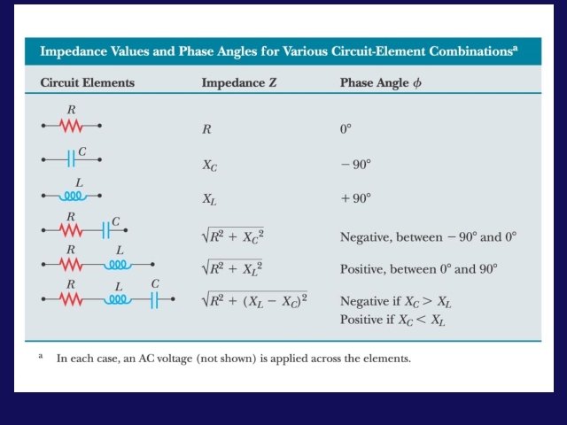
Phasors • R: V in phase with i Þ • C: V lags i by 90° Þ • L: V leads i by 90° Þ • A phasor is a vector whose magnitude is the maximum value of a quantity (eg V or I) and which rotates counterclockwise in a 2 -d plane with angular velocity w. Recall uniform circular motion: The projections of r (on the vertical y axis) execute sinusoidal oscillation. y y w x
Suppose: Phasors for L, C, R i ß i w 0 wt i 0 w wt i 0 i i wt w
w - dependence in AC Circuits • The maximum current & voltage are related via the impedence Z • Currents AC-circuits as a function of frequency:
24 -5 RLC Circuits • Phasor diagram – useful to analyze an RLC circuit • Follow the loop • Total V V= VR + VL+ VC = Z Imax – VR = R Imax (in phase) – VL= XL Imax (leads by 90 o) – VC= XC Imax (lags by 90 o)
Phasors: LCR • The phasor diagram has been relabeled in terms of the reactances defined from: The unknowns (Imax, f) can now be solved for graphically since the vector sum of the voltages VL + VC + VR must sum to the driving emf e.
Phasors: LCR Imax (XL-XC) Vmax = Imax Z Þ f Imax R
24 -5 RLC Circuits • The phase angle for an RLC circuit is: • If XL = XC, the phase angle is zero, and the voltage and current are in phase. • The power factor:
Phasors: Tips • This phasor diagram was drawn as a snapshot of time t=0 with the voltages being given as the projections along the y -axis. • Sometimes, in working problems, it is easier to draw the diagram at a time when the current is along the x-axis (when i=0). Imax. XL Vmax f Imax. R Imax. XC “Full Phasor Diagram” From this diagram, we can also create a triangle which allows us to calculate the impedance Z: Z | XL-XC | | R “ Impedance Triangle”
24 -5 RLC Circuits • At high frequencies, the capacitive reactance is very small, while the inductive reactance is very large. The opposite is true at low frequencies.
Lecture 12, ACT 1 • A series LCR circuit driven by emf e = e 0 sinwt produces a current i=imsin(wt-f). The phasor diagram for the current at t=0 is shown to the right. – At which of the following times is VC, the magnitude of the voltage across the capacitor, a maximum? i t=0 (a) t=tc t=tb i i (b) (c) t=0 f i
24 -6: Resonance - LC Circuits • Consider the LC and RC series circuits shown: C R C L • Suppose that the circuits are formed at t=0 with the capacitor C charged to a value Q. Claim is that there is a qualitative difference in the time development of the currents produced in these two cases. Why? ? • Consider from point of view of energy! • In the RC circuit, any current developed will cause energy to be dissipated in the resistor. • In the LC circuit, there is NO mechanism for energy dissipation; energy can be stored both in the capacitor and the inductor!
RC/LC Circuits i i Q +++ Q C +++ --- C R LC: current oscillates RC: current decays exponentially 0 i -i 0 0 1 t L t
LC Oscillations (qualitative) + + - - C L C Þ Ý C L ß L Ü - - + + C L
Energy transfer in a resistanceless, nonradiating LC circuit. The capacitor has a charge Qmax at t = 0, the instant at which the switch is closed. The mechanical analog of this circuit is a block–spring system.
LC Oscillations (quantitative) • What do we need to do to turn our qualitative knowledge into quantitative knowledge? + + - - C • What is the frequency w of the oscillations (when R=0)? • The rms voltages across the capacitor and inductor must be the same; therefore, we can calculate the resonant frequency. L
LC Oscillations (quantitative: requires calculus) i • Begin with the loop rule: e. C= -Q/C Q + + - - C L e. L= -L DI / Dt • Guess solution: (just harmonic oscillator!) remember: where: • w 0 determined from equation • , Q 0 determined from initial conditions If C fully charged with , Q 0 at t=0, =0. • Procedure: differentiate above form for Q and substitute into loop equation to find w 0.
Review: LC Oscillations i • Guess solution: (just harmonic oscillator!) Q where: + + - - C • w 0 determined from equation • , Q 0 determined from initial conditions which we could have determined from the mass on a spring result: L
The energy in LC circuit conserved ! When the capacitor is fully charged: When the current is at maximum (Io): The maximum energy stored in the capacitor and in the inductor are the same: At any time:
Lecture 12, ACT 2 • At t=0 the capacitor has charge Q 0; the resulting oscillations have frequency w 0. The maximum current in the circuit during these oscillations has value I 0. – What is the relation between w and w 2 , the 1 A frequency of oscillations when 0 the initial charge = 2 Q 0 ? (a) w 2 = 1/2 w 0 (b) w 2 = w 0 (c) w 2 = 2 w 0
Lecture 12, ACT 2 • At t=0 the capacitor has charge Q 0; the resulting oscillations have frequency w 0. The maximum current in the circuit during these oscillations has value I 0. 1 B • What is the relation between I 0 and I 2 , the maximum current in the circuit when the initial charge = 2 Q 0 ? (a) I 2 = I 0 (b) I 2 = 2 I 0 (c) I 2 = 4 I 0
Resonance • For fixed R, C, L the current im will be a maximum at the resonant frequency w 0 which makes the impedance Z purely resistive. ie: reaches a maximum when: XL=XC the frequency at which this condition is obtained is given from: Þ • Note that this resonant frequency is identical to the natural frequency of the LC circuit by itself! • At this frequency, the current and the driving voltage are in phase!
24 -6 Resonance in Electrical Circuits • In an RLC circuit with an ac power source, the impedance is a minimum at the resonant frequency: XL=XC
Resonance The current in an LCR circuit depends on the values of the elements and on the driving frequency through the relation Z | XL-XC | | R “ Impedance Triangle” Suppose you plot the current versus w, the source voltage frequency, you would get: m / R 0 R=Ro im 0 R=2 Ro 0 1 wx 2 w 2 o
Power in LCR Circuit • The power supplied by the emf in a series LCR circuit depends on the frequency w. It will turn out that the maximum power is supplied at the resonant frequency w 0. • The instantaneous power (for some frequency, w) delivered at time t is given by: Remember what this stands for • The most useful quantity to consider here is not the instantaneous power but rather the average power delivered in a cycle. • To evaluate the average on the right, we first expand the sin(wt-f) term.
Power in LCR Circuit • Expanding, • Taking the averages, +1 (Integral of Product of even and odd function = 0) • Generally: 0 -10 • sinwtcoswt wt 2 p Putting it all back together again, 1/2 0 +1 sin 2 wt 0 -1 0 wt 2 p
Power in LCR Circuit • The power can be expressed in term of i max: Þ • This result is often rewritten in terms of rms values: Þ • Power delivered depends on the phase, , the “power factor” • phase depends on the values of L, C, R, and w
Fields from Circuits? • We have been focusing on what happens within the circuits we have been studying (eg currents, voltages, etc. ) • What’s happening outside the circuits? ? – We know that: » charges create electric fields and » moving charges (currents) create magnetic fields. – Can we detect these fields? – Demos: » We saw a bulb connected to a loop glow when the loop came near a solenoidal magnet. » Light spreads out and makes interference patterns. Do we understand this?
Application of Resonance o Tuning a radio o A varying capacitor changes the resonance frequency of the tuning circuit in your radio to match the station to be received o Metal Detector o The portal is an inductor, and the resonant frequency is set to a condition with no metal present o When metal is present, it changes the effective inductance, which changes the current o The change in current is detected an alarm sounds
Problem Solution Method: Five Steps: 1) Focus on the Problem - draw a picture – what are we asking for? 2) Describe the physics - what physics ideas are applicable what are the relevant variables known and unknown 3) Plan the solution - what are the relevant physics equations 4) Execute the plan - solve in terms of variables solve in terms of numbers 5) Evaluate the answer - are the dimensions and units correct? do the numbers make sense?
Recap of Today’s Topic : • Announcements: Team problems start this Thursday – Team 1: Hend Ouda, Mike Glinski, Stephanie Auger – Team 2: Analiese Bruder, Kristen Dean, Alison Smith • Office hours: Monday 2: 30 -3: 30 Thursday 3: 00 -4: 00 • Homework #5: due this coming Friday • Midterm 1: Thursday March 1 st (in class) – Review session Tuesday Feb. 27 (+ Team problems) – Midterm sample + To-Know sheet on web already • Chapter 24: AC circuits – – AC voltage, current + phaser and RMS values C & L in AC circuits + RC & RL circuits RLC circuits resonances