Physics 05 Electric Currents BY HEI MAN KWOK

Physics 05: Electric Currents BY HEI MAN KWOK 12 N 03 S

5. 1 ELECTRIC POTENTIAL DIFFERENCE, CURRENT AND RESISTANCE

Model of electric conduction in a metal – energy transfer 1. 2. 3. 4. 5. Charge carriers have kinetic energy These collide with lattice ions Increasing amplitude of vibrations This is seen in an increase in temperature Electrons loses it energy and transfers it to thermal energy Speed of electron through a conductor = drift speed
 •")
Charge (Q) •

Electric Potential Difference •

• Change in potential energy when a charge moves between two points at different potentials
 •")
Electronvolt (e. V) •
 •")
Electric Current (in a conductor) •

Resistance •

Resistivity •

Ohm’s Law • The ratio of potential difference to current are proportional at constant temperature • V = IR • Eg. Wires and fixed resistors

Non-Ohmic – Filament lamp • As current increases, temperature increases, atoms vibrate more, collisions between electrons and metal atoms are more frequent so resistance increases, and graph flattens • The current is not directly proportional to the voltage – disobeys ohm’s law • Graph = symmetrical

Diode • One way value for electrons • No current when negative V • Positive = current flows easily as diode has low resistance above about 0. 7 V • LEDs also one way : D
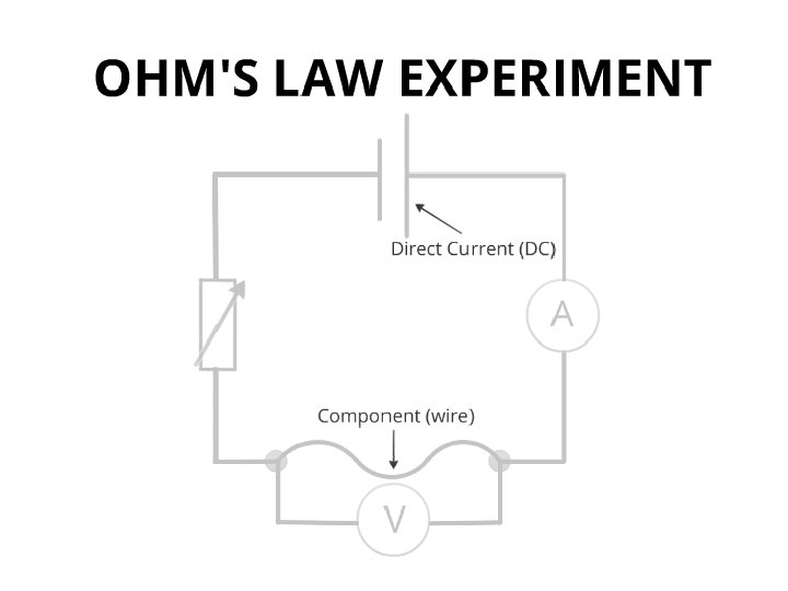

Component’s Potential Difference Cannot be equal to the p. d. of the battery: • Some voltage will be lost to internal resistance and/ or the resistance in wires Cannot equal to zero • Low voltage requires very high resistance, max. resistance of the variable resistor cannot be infinite, there will always be some resistance from the component

5. 2 ELECTRIC CIRCUITS
 • Work done per unit charge made available by the energy")
Electromotive Force (emf) • Work done per unit charge made available by the energy source (cell or battery) • Power supplied by the cell per unit current from the cell

Law of Conservation of Energy •

Internal Resistance •

Finding Internal Resistance Experimentally • V = E – Ir • By recording values of current and terminal pd as the external resistance changes you can plot the graph and find the internal resistance and the emf of the cell. • If there is more than one cell in series the internal resistances of the cells must be added.

Power Dissipated •

Power Delivered •

V, I, R in Series •

V, I, R in Parallel •

Ideal Ammeter • Zero resistance so it does not change the current in the circuit • Connected in series so the current will flow through the ammeter as it flows through a component

Ideal Voltmeter • Infinite resistance so it does not take any current from the circuit • Connected in parallel to see the difference in potential energy between two points

Thermistor and LDR • Made of semi-conducting material • Heat and light frees more charge carriers: as the temperature/ light intensity increases, the resistance decreases • The current is not directly proportional to the voltage LDR Thermistor

Strain Gauge • Think metal wire • If stretch – length increases and crosssectional area decreases = increase in resistance

Potential Divider
- Slides: 29