Physical Optics The wave nature of light Interference


- Slides: 25

Physical Optics The wave nature of light Interference Diffraction Polarization

Huygens’ Principle • Every point on a propagating wavefront serves as the source of spherical wavelets, such that the wavelets at sometime later is the envelope of these wavelets. • If a propagating wave has a particular frequency and speed, the secondary wavelets have that same frequency and speed. “Isotropic”

Diffraction a • Diffraction – Bending of light into the shadow region • Grimaldi - 17 th Century observation of diffraction • Diffraction vs. Refraction?

Explanation of Snell’s Law

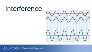
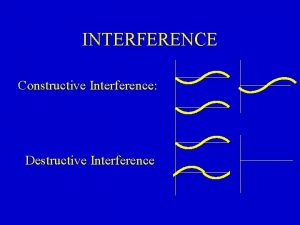
Superposition of waves Constructive Interference Destructive Interference

Conditions for Interference • To observe interference in light waves, the following two conditions must be met: 1) The sources must be coherent • They must maintain a constant phase with respect to each other 2) The sources should be monochromatic • Monochromatic means they have a single wavelength

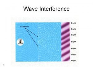
Young’s Experiment

Young’s Experiment

Young’s Experiment Maxima occur when: maxima Minima occur when:

What the pattern looks like

Intensity Distribution, Electric Fields • The magnitude of each wave at point P can be found – E 1 = Eo sin ωt – E 2 = Eo sin (ωt + φ) – Both waves have the same amplitude, Eo

Intensity Distribution, Resultant Field • The magnitude of the resultant electric field comes from the superposition principle – EP = E 1+ E 2 = Eo[sin ωt + sin (ωt + φ)] • This can also be expressed as – EP has the same frequency as the light at the slits – The magnitude of the field is multiplied by the factor 2 cos (φ / 2)

Intensity Distribution, Equation • The expression for the intensity comes from the fact that the intensity of a wave is proportional to the square of the resultant electric field magnitude at that point • The intensity therefore is

Resulting Interference Pattern • The light from the two slits forms a visible pattern on a screen • The pattern consists of a series of bright and dark parallel bands called fringes • Constructive interference occurs where a bright fringe occurs • Destructive interference results in a dark fringe

Example A He-Ne Laser has a wavelength of 633 nm. Two slits are placed immediately in front of the laser and an interference pattern is observed on a screen 10 m away. If the first bright band is observed 1 cm from the central bright fringe, how far apart are the two slits? At what angle Q is the fourth dark band found?

Thin Films Constructive Interference (maxima) Destructive Interference (minima)

Phase shift on reflection External Reflection Internal Reflection Now, If one reflection is internal and one reflection is external half wavelength path differences will result in constructive interference

Phase Changes Due To Reflection • An electromagnetic wave undergoes a phase change of 180° upon reflection from a medium of higher index of refraction than the one in which it was traveling – Analogous to a pulse on a string reflected from a rigid support

Lloyd’s Mirror • An arrangement for producing an interference pattern with a single light source • Waves reach point P either by a direct path or by reflection • The reflected ray can be treated as a ray from the source S’ behind the mirror

Lloyd’s Mirror

Interference in Thin Films Again • • Assume the light rays are traveling in air nearly normal to the two surfaces of the film Ray 1 undergoes a phase change of 180° with respect to the incident ray Ray 2, which is reflected from the lower surface, undergoes no phase change with respect to the incident wave For constructive interference d=2 t = (m + ½)λn (m = 0, 1, 2 …) • This takes into account both the difference in optical path length for the two rays and the 180° phase change • For destructive interference d=2 t = mλn (m = 0, 1, 2 …)

Newton’s Rings Maxima - bright Minima - dark

Newton’s Rings Minima Newtons rings are a special case of Fizeau fringes. They are useful for testing surface accuracy of a lens. Maxima

Wedges – Fringes of Equal Thickness Minima (destructive) Maxima (constructive) Fringes of this type are also known as Fizeau fringes

Presented By Prof. Swapan Kr. Gupta SHD College Pathankhali
 Difference between ray optics and wave optics
 Venn diagram of geometric optics and physical optics
 Proactive interference example
 Retroactive vs proactive interference
 Http //vsg.quasihome.com
 Wave optics b.sc physics
 Nature of light
 Energy of light wave
 Single ray
 What is the difference between luminous and non luminous
 Bill nye reflection and refraction
 Light and optics notes
 Interference wave behavior
 Wave interference investigation
 Mechanical wave interference
 Characteristics of mechanical waves
 Interference of waves
 Light light light chapter 23
 Light light light chapter 22
 Light light light chapter 22
 Interference of light engineering physics
 Interference of light
 Light is electromagnetic radiation true or false
 Carbon dioxide temperature
 Difference between full wave and half wave rectifier
 Transverse and longitudinal waves both *

