
Physical Layer Shivkumar Kalyanaraman Rensselaer Polytechnic Institute shivkumaecse

- Slides: 33
Physical Layer Shivkumar Kalyanaraman Rensselaer Polytechnic Institute shivkuma@ecse. rpi. edu http: //www. ecse. rpi. edu/Homepages/shivkuma Based in part upon the slides of Prof. Raj Jain (OSU) Shivkumar Kalyanaraman Rensselaer Polytechnic Institute 1 -1
Overview q The physical layer problem q Theory: Frequency vs time domain, Information theory, Nyquist criterion, Shannon’s theorem q Link characteristics: bandwidth, error rate, attenuation, dispersion q Transmission Media: q UTP, Coax, Fiber q Wireless: Satellite Shivkumar Kalyanaraman Rensselaer Polytechnic Institute 1 -2
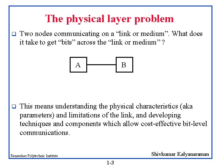
The physical layer problem q Two nodes communicating on a “link or medium”. What does it take to get “bits” across the “link or medium” ? A q B This means understanding the physical characteristics (aka parameters) and limitations of the link, and developing techniques and components which allow cost-effective bit-level communications. Shivkumar Kalyanaraman Rensselaer Polytechnic Institute 1 -3
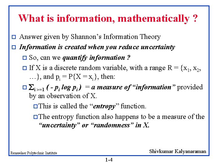
What is information, mathematically ? o o Answer given by Shannon’s Information Theory Information is created when you reduce uncertainty o So, can we quantify information ? o If X is a discrete random variable, with a range R = {x 1, x 2, …}, and pi = P{X = xi}, then: o i >=1 ( - pi log pi ) = a measure of “information” provided by an observation of X. o This is called the “entropy” function. o The entropy function also happens to be a measure of the “uncertainty” or “randomness” in X. Shivkumar Kalyanaraman Rensselaer Polytechnic Institute 1 -4
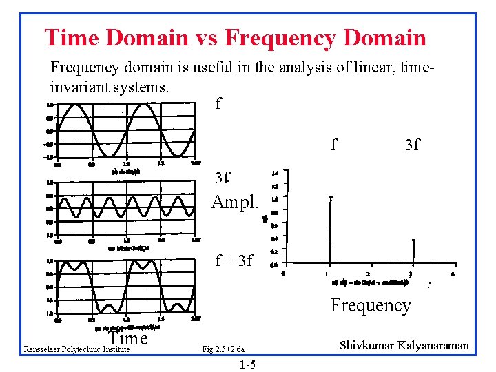
Time Domain vs Frequency Domain Frequency domain is useful in the analysis of linear, timeinvariant systems. f f 3 f 3 f Ampl. f + 3 f Frequency Time Rensselaer Polytechnic Institute Fig 2. 5+2. 6 a 1 -5 Shivkumar Kalyanaraman
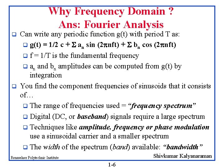
Why Frequency Domain ? Ans: Fourier Analysis q q Can write any periodic function g(t) with period T as: q g(t) = 1/2 c + an sin (2 nft) + bn cos (2 nft) q f = 1/T is the fundamental frequency q an and bn amplitudes can be computed from g(t) by integration You find the component frequencies of sinusoids that it consists of… q The range of frequencies used = “frequency spectrum” q Digital (DC, or baseband) signals require a large spectrum q Techniques like amplitude, frequency or phase modulation use a sinusoidal carrier and a smaller spectrum q The width of the spectrum (band) available: “bandwidth” Shivkumar Kalyanaraman Rensselaer Polytechnic Institute 1 -6
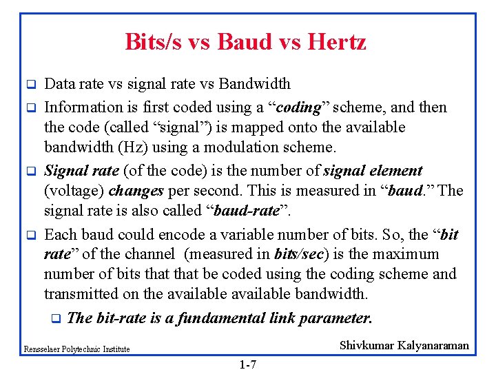
Bits/s vs Baud vs Hertz q q Data rate vs signal rate vs Bandwidth Information is first coded using a “coding” scheme, and then the code (called “signal”) is mapped onto the available bandwidth (Hz) using a modulation scheme. Signal rate (of the code) is the number of signal element (voltage) changes per second. This is measured in “baud. ” The signal rate is also called “baud-rate”. Each baud could encode a variable number of bits. So, the “bit rate” of the channel (measured in bits/sec) is the maximum number of bits that be coded using the coding scheme and transmitted on the available bandwidth. q The bit-rate is a fundamental link parameter. Shivkumar Kalyanaraman Rensselaer Polytechnic Institute 1 -7
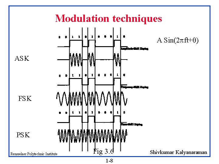
Modulation techniques A Sin(2 ft+ ) ASK FSK PSK Rensselaer Polytechnic Institute Fig 3. 6 1 -8 Shivkumar Kalyanaraman
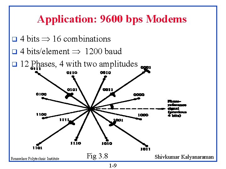
Application: 9600 bps Modems 4 bits 16 combinations q 4 bits/element 1200 baud q 12 Phases, 4 with two amplitudes q Rensselaer Polytechnic Institute Fig 3. 8 Shivkumar Kalyanaraman 1 -9
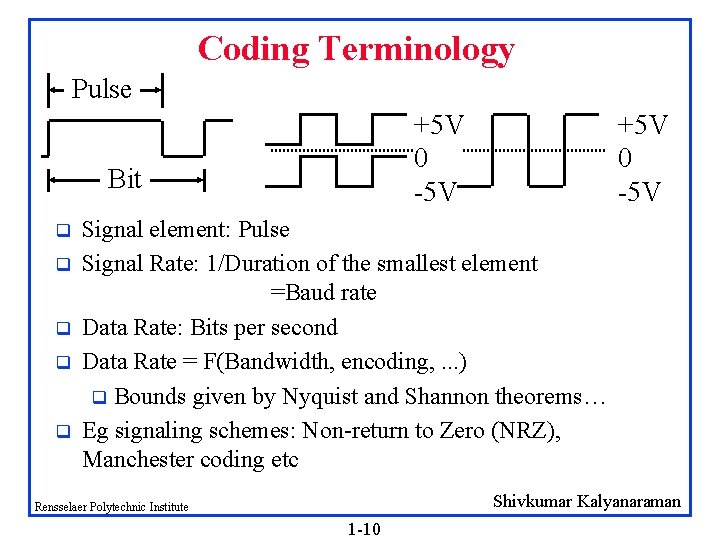
Coding Terminology Pulse +5 V 0 -5 V Bit q q q +5 V 0 -5 V Signal element: Pulse Signal Rate: 1/Duration of the smallest element =Baud rate Data Rate: Bits per second Data Rate = F(Bandwidth, encoding, . . . ) q Bounds given by Nyquist and Shannon theorems… Eg signaling schemes: Non-return to Zero (NRZ), Manchester coding etc Shivkumar Kalyanaraman Rensselaer Polytechnic Institute 1 -10
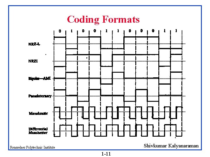
Coding Formats Shivkumar Kalyanaraman Rensselaer Polytechnic Institute 1 -11
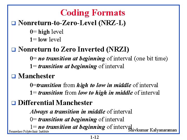
Coding Formats q Nonreturn-to-Zero-Level (NRZ-L) 0= high level 1= low level q Nonreturn to Zero Inverted (NRZI) 0= no transition at beginning of interval (one bit time) 1= transition at beginning of interval q Manchester 0=transition from high to low in middle of interval 1= transition from low to high in middle of interval q Differential Manchester Always a transition in middle of interval 0= transition at beginning of interval 1= no transition at beginning of interval Shivkumar Kalyanaraman Rensselaer Polytechnic Institute 1 -12
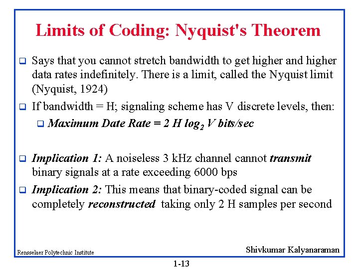
Limits of Coding: Nyquist's Theorem q q Says that you cannot stretch bandwidth to get higher and higher data rates indefinitely. There is a limit, called the Nyquist limit (Nyquist, 1924) If bandwidth = H; signaling scheme has V discrete levels, then: q Maximum Date Rate = 2 H log 2 V bits/sec Implication 1: A noiseless 3 k. Hz channel cannot transmit binary signals at a rate exceeding 6000 bps Implication 2: This means that binary-coded signal can be completely reconstructed taking only 2 H samples per second Shivkumar Kalyanaraman Rensselaer Polytechnic Institute 1 -13
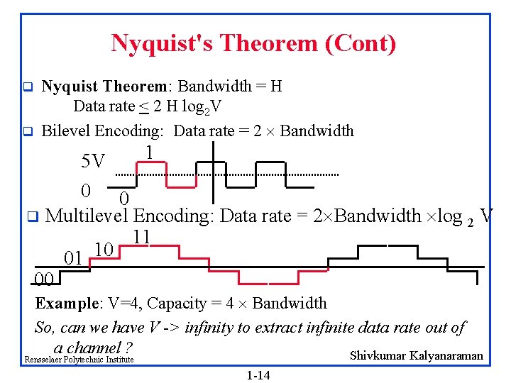
Nyquist's Theorem (Cont) q q Nyquist Theorem: Bandwidth = H Data rate < 2 H log 2 V Bilevel Encoding: Data rate = 2 Bandwidth 1 5 V 0 0 q Multilevel Encoding: Data rate = 2 Bandwidth log 2 V 11 01 10 00 Example: V=4, Capacity = 4 Bandwidth So, can we have V -> infinity to extract infinite data rate out of a channel ? Shivkumar Kalyanaraman Rensselaer Polytechnic Institute 1 -14
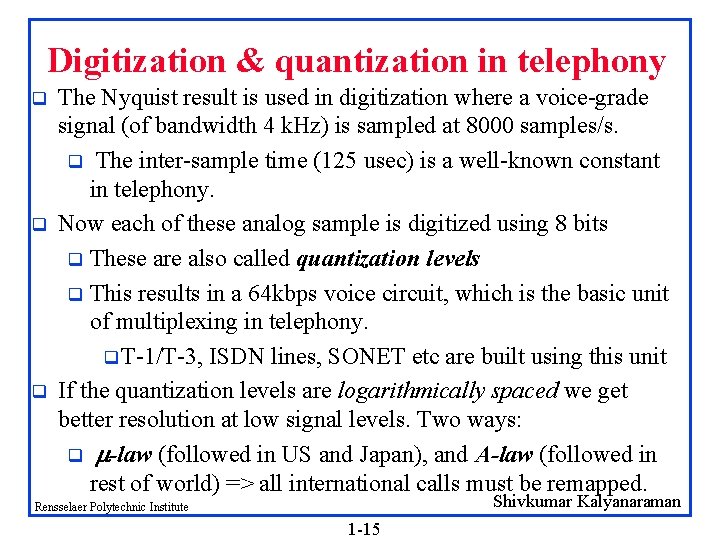
Digitization & quantization in telephony q q q The Nyquist result is used in digitization where a voice-grade signal (of bandwidth 4 k. Hz) is sampled at 8000 samples/s. q The inter-sample time (125 usec) is a well-known constant in telephony. Now each of these analog sample is digitized using 8 bits q These are also called quantization levels q This results in a 64 kbps voice circuit, which is the basic unit of multiplexing in telephony. q T-1/T-3, ISDN lines, SONET etc are built using this unit If the quantization levels are logarithmically spaced we get better resolution at low signal levels. Two ways: q -law (followed in US and Japan), and A-law (followed in rest of world) => all international calls must be remapped. Shivkumar Kalyanaraman Rensselaer Polytechnic Institute 1 -15
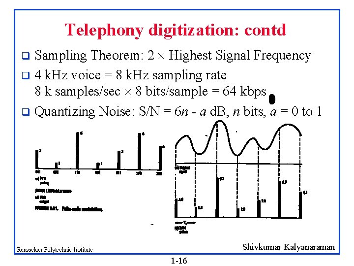
Telephony digitization: contd Sampling Theorem: 2 Highest Signal Frequency q 4 k. Hz voice = 8 k. Hz sampling rate 8 k samples/sec 8 bits/sample = 64 kbps q Quantizing Noise: S/N = 6 n - a d. B, n bits, a = 0 to 1 q Shivkumar Kalyanaraman Rensselaer Polytechnic Institute 1 -16
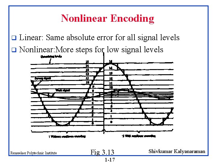
Nonlinear Encoding Linear: Same absolute error for all signal levels q Nonlinear: More steps for low signal levels q Rensselaer Polytechnic Institute Fig 3. 13 1 -17 Shivkumar Kalyanaraman
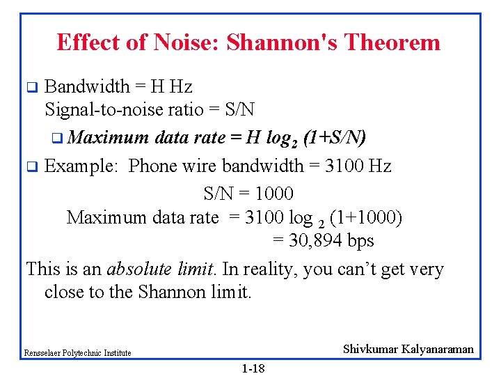
Effect of Noise: Shannon's Theorem Bandwidth = H Hz Signal-to-noise ratio = S/N q Maximum data rate = H log 2 (1+S/N) q Example: Phone wire bandwidth = 3100 Hz S/N = 1000 Maximum data rate = 3100 log 2 (1+1000) = 30, 894 bps This is an absolute limit. In reality, you can’t get very close to the Shannon limit. q Shivkumar Kalyanaraman Rensselaer Polytechnic Institute 1 -18
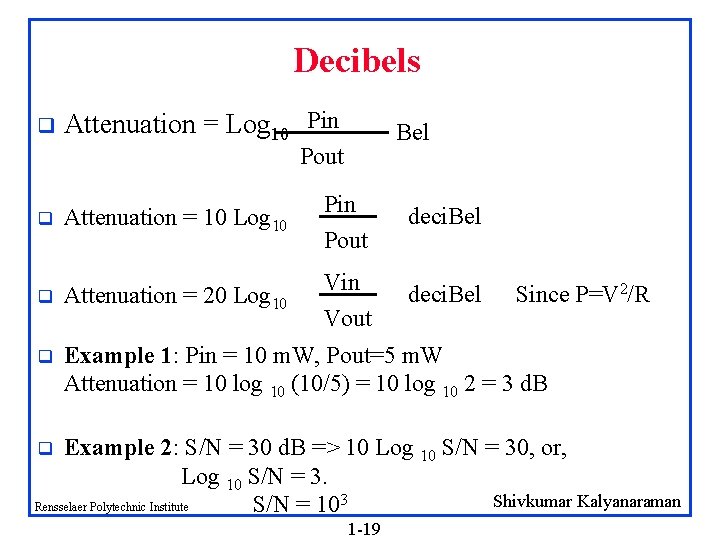
Decibels q Attenuation = Log 10 Pin Bel Pout q Attenuation = 10 Log 10 Pin Pout q Attenuation = 20 Log 10 Vin Vout q Example 1: Pin = 10 m. W, Pout=5 m. W Attenuation = 10 log 10 (10/5) = 10 log 10 2 = 3 d. B deci. Bel Since P=V 2/R Example 2: S/N = 30 d. B => 10 Log 10 S/N = 30, or, Log 10 S/N = 3. Shivkumar Kalyanaraman Rensselaer Polytechnic Institute S/N = 103 q 1 -19
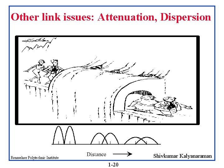
Other link issues: Attenuation, Dispersion Shivkumar Kalyanaraman Rensselaer Polytechnic Institute 1 -20
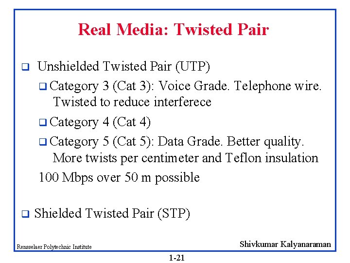
Real Media: Twisted Pair q q Unshielded Twisted Pair (UTP) q Category 3 (Cat 3): Voice Grade. Telephone wire. Twisted to reduce interferece q Category 4 (Cat 4) q Category 5 (Cat 5): Data Grade. Better quality. More twists per centimeter and Teflon insulation 100 Mbps over 50 m possible Shielded Twisted Pair (STP) Shivkumar Kalyanaraman Rensselaer Polytechnic Institute 1 -21
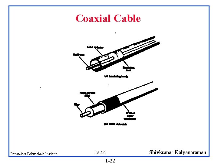
Coaxial Cable Rensselaer Polytechnic Institute Fig 2. 20 1 -22 Shivkumar Kalyanaraman
Baseband Coaxial Cable Better shielding longer distances and higher speeds q 50 -ohm cable used for digital transmission q Construction and shielding high bandwidth and noise immunity q For 1 km cables, 1 -2 Gbps is feasible q Longer cable Lower rate q Shivkumar Kalyanaraman Rensselaer Polytechnic Institute 1 -23
Broadband Coaxial Cable (Cont) 75 -ohm cable used for analog transmission (standard cable TV) q Cables go up to 450 MHz and run to 100 km because they carry analog signals q System is divided up into multiple channels, each of which can be used for TV, audio or converted digital bitstream q Need analog amplifiers to periodically strengthen signal q Shivkumar Kalyanaraman Rensselaer Polytechnic Institute 1 -24
Dual cable systems have 2 identical cables and a headend at the root of the cable tree q Other systems allocate different frequency bands for inbound and outbound communication, e. g. subsplit systems, midsplit systems q Shivkumar Kalyanaraman Rensselaer Polytechnic Institute 1 -25
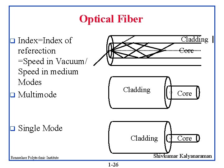
Optical Fiber Cladding Index=Index of referection =Speed in Vacuum/ Speed in medium Modes q Multimode q q Core Cladding Core Single Mode Cladding Core Shivkumar Kalyanaraman Rensselaer Polytechnic Institute 1 -26
Fiber Optics With current fiber technology, the achievable bandwidth is more than 50, 000 Gbps q 1 Gbps is used because of conversion from electrical to optical signals q Error rates are negligible q Optical transmission system consists of light source, transmission medium and detector q Shivkumar Kalyanaraman Rensselaer Polytechnic Institute 1 -27
Pulse of light indicates a 1 -bit and absence 0 -bit q Detector generates electrical pulse when light falls on it q Refraction traps light inside the fiber q Fibers can terminate in connectors, be spliced mechanically, or be fused to form a solid connection q LEDs and semiconductor lasers can be used as sources q Tapping fiber is complex topologies such as rings or passive stars are used q Shivkumar Kalyanaraman Rensselaer Polytechnic Institute 1 -28
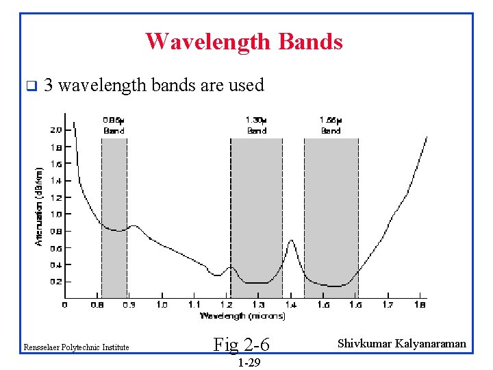
Wavelength Bands q 3 wavelength bands are used Rensselaer Polytechnic Institute Fig 2 -6 1 -29 Shivkumar Kalyanaraman
Wireless Transmission The Electromagnetic Spectrum q Radio Transmission q Microwave Transmission q Infrared and Millimeter Waves q Lightwave Transmission q Satellite Transmission q Shivkumar Kalyanaraman Rensselaer Polytechnic Institute 1 -30
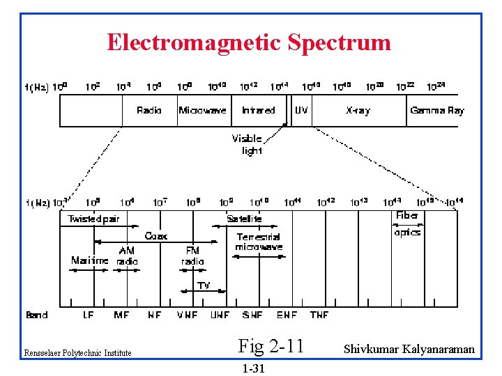
Electromagnetic Spectrum Rensselaer Polytechnic Institute Fig 2 -11 1 -31 Shivkumar Kalyanaraman
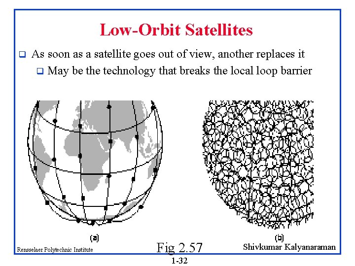
Low-Orbit Satellites q As soon as a satellite goes out of view, another replaces it q May be the technology that breaks the local loop barrier Rensselaer Polytechnic Institute Fig 2. 57 1 -32 Shivkumar Kalyanaraman
Summary q q q Link characteristics: q Bandwidth, Attenuation, Dispersion Theory: q Frequency domain and time domain q Nyquist theorem and Shannon’s Theorem q Coding, Bit, Baud, Hertz Physical Media: UTP, Coax, Fiber, Satellite Shivkumar Kalyanaraman Rensselaer Polytechnic Institute 1 -33