PHOTOVOLTAIC SYSTEMS 9 1 INTRODUCTION TO THE MAJOR


 It has high")


 The PV voltage would be : V = VB + I Ri")
- Slides: 25
PHOTOVOLTAIC SYSTEMS 9. 1 INTRODUCTION TO THE MAJOR PHOTOVOLTAIC SYSTEM TYPES The focus of this chapter is on the analysis and design of photovoltaic (PV) systems in their three most commonly encountered configurations: 1) systems that feed power directly into the utility grid, 2) stand-alone systems that charge batteries, perhaps with generator back-up, 3) applications in which the load is directly connected to the PVs as in the case for most water-pumping systems.
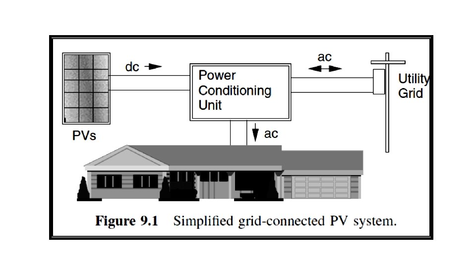
Systems that feed power directly into the utility grid; q The photovoltaics in a grid-connected system deliver dc power to a power conditioning unit (PCU) that converts dc to ac and sends power to the building. q If the PVs supply less than the immediate demand of the building, the PCU draws supplementary power from the utility grid, so demand is always satisfied. q If, at any moment, the PVs supply more power than is needed, the excess is sent back onto the grid, potentially spinning the electric meter backwards.
q Grid-connected PV systems have a number of desirable attributes: a) It has high reliability; b) It can be integrated into the building structure. c) The system is relatively simple since failure-prone batteries are not needed for back-up power. d) The power-conditioning unit also helps to keep the PVs operating at the most efficient point on their I –V curves as conditions change.
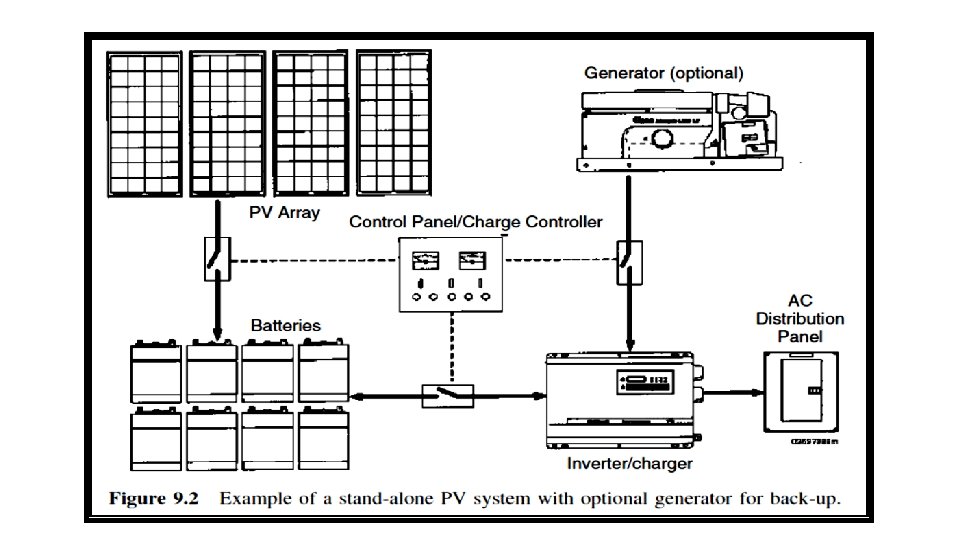
Stand-alone PV systems : Stand-alone PV systems can be very cost effective in remote locations where the only alternatives may be noisy, high-maintenance generators burning relatively expensive fuel, or extending the existing utility grid to the site, which can cost thousands of dollars per mile. Figure 9. 2 shows the stand-alone system with battery storage and a generator for back-up power. In this particular system, an inverter converts battery dc voltages into ac.
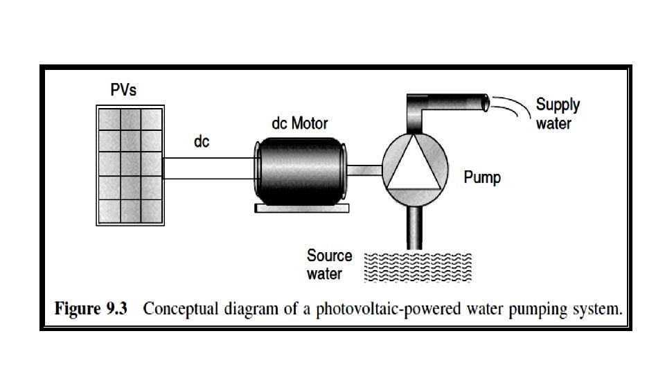
Direct connection of the load to the PVs : q The most common example is PV water pumping in which the wires from the array are connected directly to the motor running a pump (Fig. 9. 3). q There is no electric energy storage, but potential energy may be stored in a tank of water for use whenever it is needed. q These systems are the ultimate in simplicity and reliability and are the least costly as well. But they need to be carefully designed to be efficient.
Our goal in this chapter is to try to learn how to properly size photovoltaic systems to provide for these various types of loads. Power delivered by a photovoltaic system depends upon: a) Solar intensity. b) overcast conditions ( )ﻣﻠﺒﺪﺓ ﺑﺎﻟﻐﻴﻮﻡ. c) Ambient temperature. d) Wind speed. e) Type of load.
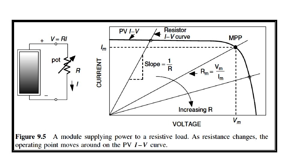
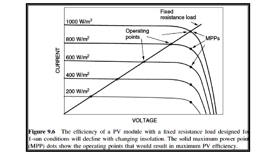
9. 2 CURRENT–VOLTAGE CURVES FOR LOADS When the I –V curve for the load is plotted onto the same graph that has the I –V curve for the PVs, the intersection point is the one spot at which both the PVs and load are satisfied. This is called the operating point. 9. 2. 1 Simple Resistive-Load I–V Curve To illustrate the importance and need for load curves, consider a simple resistive load as shown in Fig. 9. 5. As R increases, the operating point where the PV and resistance I –V curves intersect moves along the PV I –V curve from left to right. A simple way to measure the I –V curve for PV module is by using a variable resistance as the load.
Fig. 9. 6 shows, when the PV module is loaded with a fixed resistance, the operating point slips off the MPP as conditions change and the module becomes less and less efficient. Later, a device called a maximum power point tracker (MPPT) will be introduced, the purpose of which is to keep the PVs operating at their highest efficiency point at all times.
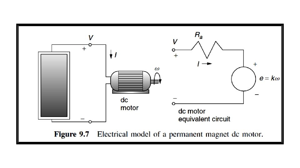
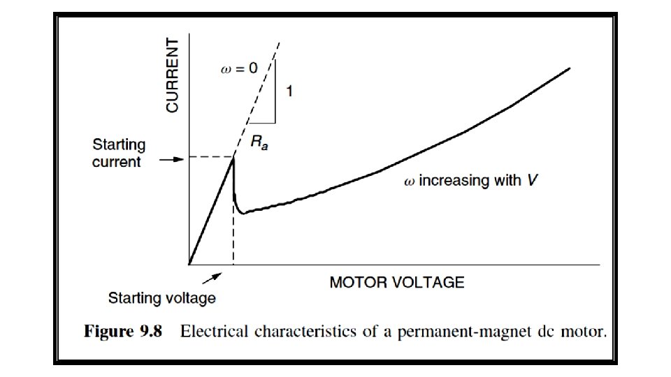
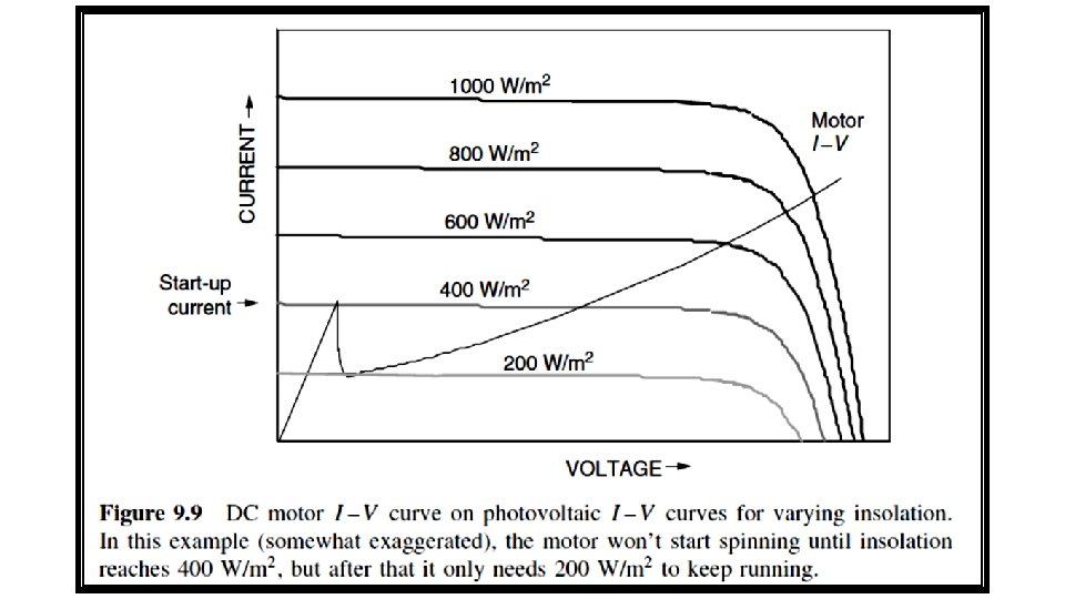
9. 2. 2 DC Motor I–V Curve The voltage–current relationship for the dc motor is: The electrical characteristic curve of a dc motor is shown in Fig. 9. 8. The I –V curve of the dc motor is superimposed on a set of photovoltaic I –V curves as in Fig. 9. 9. Notice that the motor doesn’t have enough current to overcome static friction until insolation reaches at least 400 W/m 2. Once it starts spinning, however, it only needs about 200 W/m 2 to keep running.
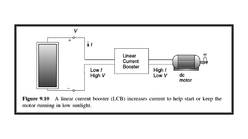
q This could mean that a fair amount of insolation is unusable in the morning while the motor struggles to break loose. q There is a device, called a linear current booster (LCB), useful when current delivered to the motor is insufficient to overcome friction (Fig. 9. 10). q The LCB can provide sufficient current to start the motor in the morning where low insolation is available.
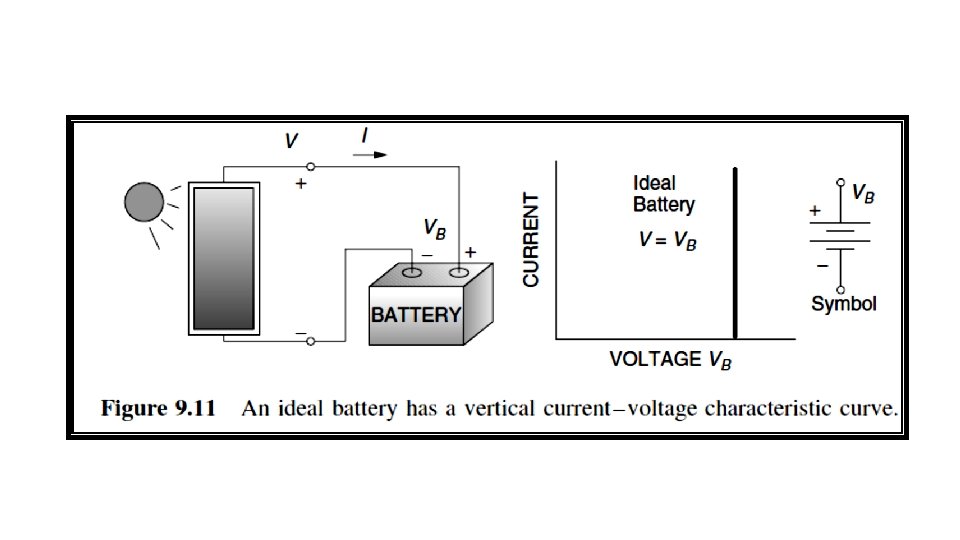
9. 2. 3 Battery I–V Curves q Since PVs only provide power during the daylight hours and many applications require energy when the sun isn’t shining, some method of energy storage often is needed. q For a water pumping system, this might be the potential energy of water stored in a tank. q For most off-grid applications, however, energy is stored in batteries for use whenever it is needed. q An ideal battery is one in which the voltage remains constant no matter how much current is drawn.
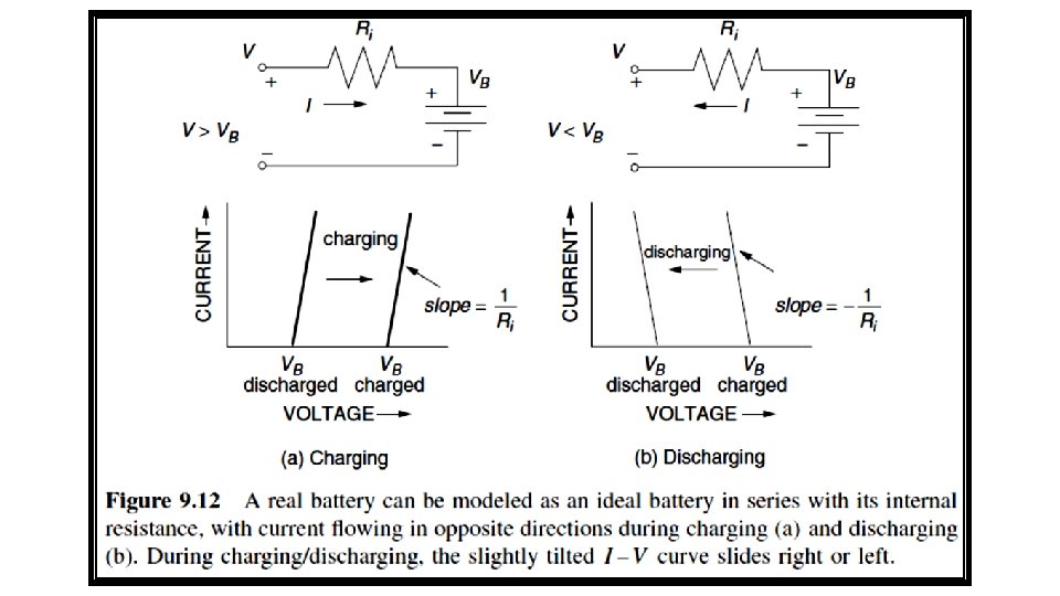
q This means that it will have an I –V curve that is simply a straight up-and-down line as shown in Fig. 9. 11. q A real battery, on the other hand, has some internal resistance and is often modeled with an equivalent circuit consisting of an ideal battery of voltage VB in series with some internal resistance Ri as shown in Fig. 9. 12. q During the charge cycle, with positive current flow into the battery, we can write:
Example 9. 1 Charging a 12 -volt Battery. Suppose that a nearly depleted 12 -V lead-acid battery has an opencircuit voltage of 11. 7 V and an internal resistance of 0. 03 Ω. a) What voltage would a PV module operate when delivering 6 A to the battery? b) If 20 A is drawn from a fully charged battery with open-circuit voltage 12. 7 V, what voltage would the PV module operate at?
Solution a) The PV voltage would be : V = VB + I Ri = 11. 7 + 0. 03 × 6 = 11. 88 V b) While drawing 20 A after VB has reached 12. 7 V, the output voltage of the battery would be : Vload = VB - I Ri = 12. 7 – 20 x 0. 03 = 12. 1 V ============== If the system has a charge controller, it will automatically prevent overcharging of the batteries.