
Photogrammetry 2 nd Year Civil Flight Planning By

Photogrammetry 2 nd Year- Civil • Flight Planning By D. Kamal M. Ahmed

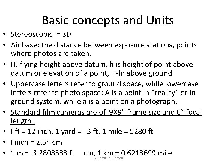
Basic concepts and Units • Stereoscopic = 3 D • Air base: the distance between exposure stations, points where photos are taken. • H: flying height above datum, h is height of point above datum or elevation of a point, H-h: above ground • Uppercase letters refer to ground space, while lowercase letters refer to photo space: A is a point in “reality” or in ground system, while a is a point on a photograph. • Standard film cameras are of 9 X 9” frame size and 6” focal length • I ft = 12 inch, 1 yard = 3 ft, 1 mile = 5280 ft • I inch = 2. 54 cm • 1 m = 3. 2808333 ft cm, D. 1 Kamalkm = 0. 6213699 mile M. Ahmed
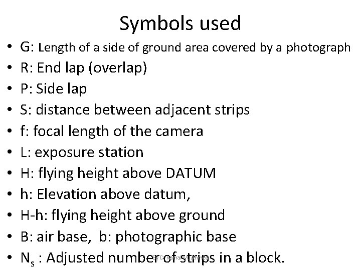
Symbols used • • • G: Length of a side of ground area covered by a photograph R: End lap (overlap) P: Side lap S: distance between adjacent strips f: focal length of the camera L: exposure station H: flying height above DATUM h: Elevation above datum, H-h: flying height above ground B: air base, b: photographic base Ns : Adjusted number of strips in a block. By D. Kamal M. Ahmed
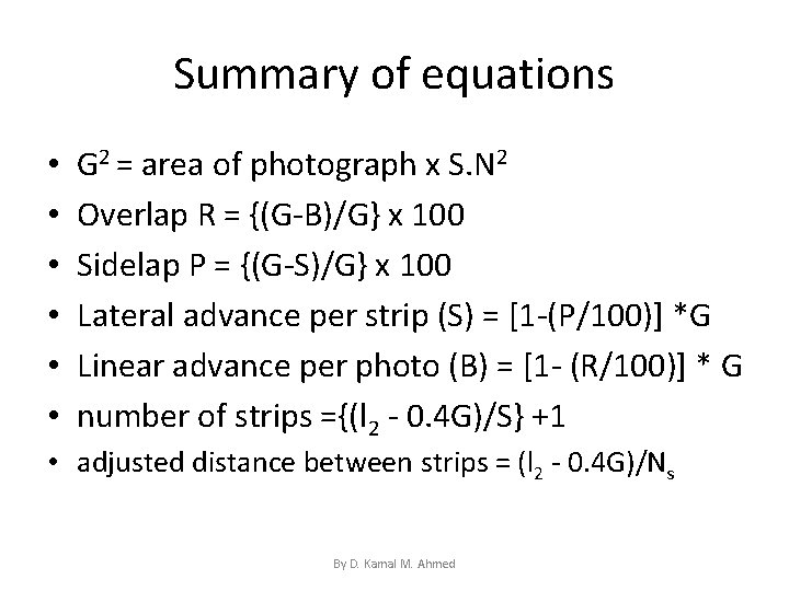
Summary of equations • • • G 2 = area of photograph x S. N 2 Overlap R = {(G-B)/G} x 100 Sidelap P = {(G-S)/G} x 100 Lateral advance per strip (S) = [1 -(P/100)] *G Linear advance per photo (B) = [1 - (R/100)] * G number of strips ={(l 2 - 0. 4 G)/S} +1 • adjusted distance between strips = (l 2 - 0. 4 G)/Ns By D. Kamal M. Ahmed

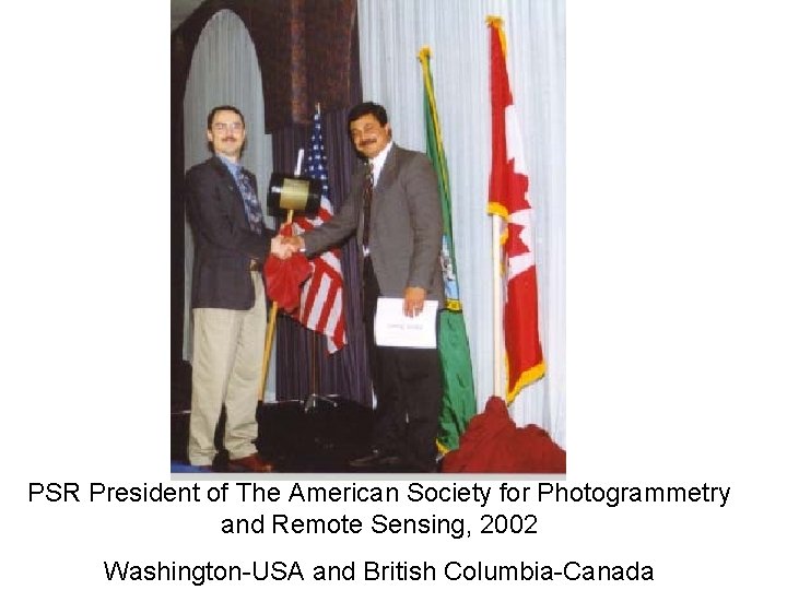
PSR President of The American Society for Photogrammetry and Remote Sensing, 2002 Washington-USA and British Columbia-Canada
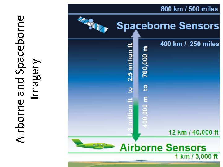
Airborne and Spaceborne Imagery
Why Flight Planning? • To ensure coverage of the area to be mapped at the required scale with no gaps, and provide stereo models by an efficient design. • The product of a flight plan is basically a map, • A flight plan will determine the spacing between successive photographs, locations of flight lines, and start and end locations of each flight line. By D. Kamal M. Ahmed
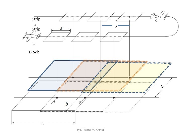
Strip + Strip B = Block G G By D. Kamal M. Ahmed
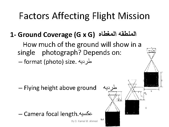
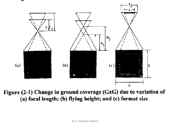
Factors Affecting Flight Mission 1 - Ground Coverage (G x G) ﺍﻟﻤﻨﻄﻘﻪ ﺍﻟﻤﻐﻄﺎﻩ How much of the ground will show in a single photograph? Depends on: – format (photo) size. ﻃﺮﺩﻳﻪ – Flying height above ground – Camera focal length. ﻋﻜﺴﻴﻪ By D. Kamal M. Ahmed ﻃﺮﺩﻳﻪ
By D. Kamal M. Ahmed
• To increase ground coverage, you increase flying height, decrease focal length, or increase the size of the photograph. • If a single photograph covers a square of side G on the ground, then; • The area on the ground G 2 covered by one photograph at a scale 1 : S. N G 2 = area of photograph x S. N 2 • For example: ground coverage G X G or G 2 of a 9 X 9” photograph taken at a scale of 1: 25, 000 is (9 X 9) X (25, 000 X 25, 000) /144 = 364, 050, 000 ft 2 (1 ft = 12 inch ﺑﻮﺻﻪ 12 = )ﺍﻟﻘﺪﻡ By D. Kamal M. Ahmed
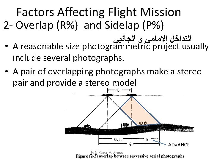
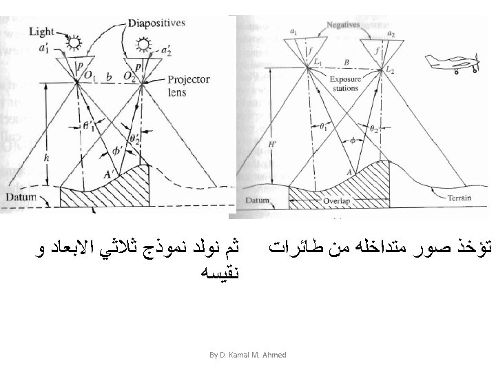
2 - Overlap (R%) and Sidelap (P%) ﺍﻟﺘﺪﺍﺧﻞ ﺍﻻﻣﺎﻣﻲ ﻭ ﺍﻟﺠﺎﻧﺒﻲ • A reasonable size photogrammetric project usually include several photographs. • A pair of overlapping photographs make a stereo pair and provide a stereo model ADVANCE By D. Kamal M. Ahmed
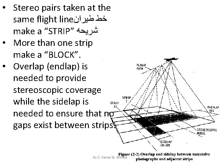
• Stereo pairs taken at the same flight line ﺧﻂ ﻃﻴﺮﺍﻥ make a “STRIP” ﺷﺮﻳﺤﻪ • More than one strip make a “BLOCK”. • Overlap (endlap) is needed to provide stereoscopic coverage while the sidelap is needed to ensure that no gaps exist between strips. By D. Kamal M. Ahmed
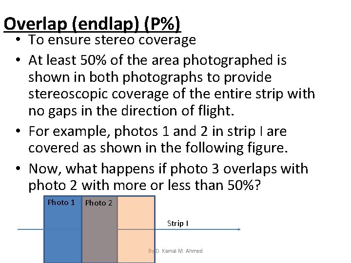
Overlap (endlap) (P%) • To ensure stereo coverage • At least 50% of the area photographed is shown in both photographs to provide stereoscopic coverage of the entire strip with no gaps in the direction of flight. • For example, photos 1 and 2 in strip I are covered as shown in the following figure. • Now, what happens if photo 3 overlaps with photo 2 with more or less than 50%? Photo 1 Photo 2 Strip I By D. Kamal M. Ahmed
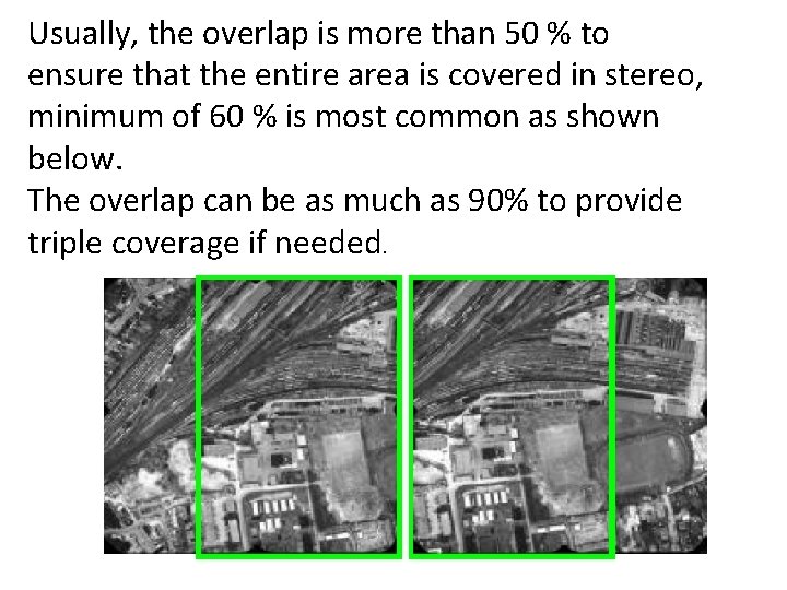
Usually, the overlap is more than 50 % to ensure that the entire area is covered in stereo, minimum of 60 % is most common as shown below. The overlap can be as much as 90% to provide triple coverage if needed. By D. Kamal M. Ahmed
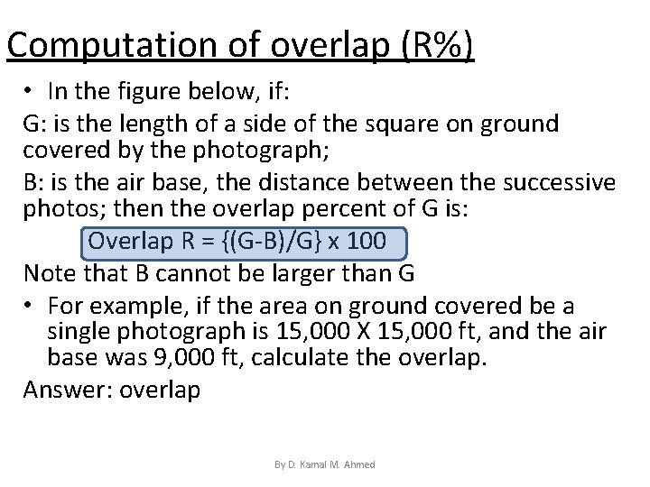
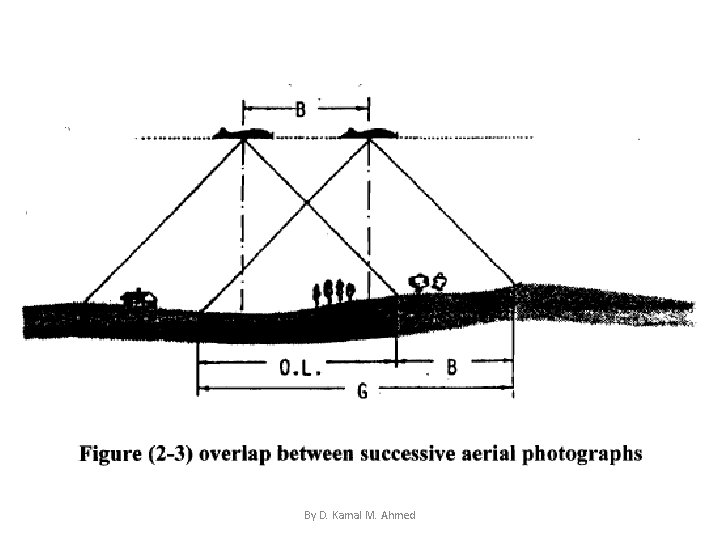
Computation of overlap (R%) • In the figure below, if: G: is the length of a side of the square on ground covered by the photograph; B: is the air base, the distance between the successive photos; then the overlap percent of G is: Overlap R = {(G-B)/G} x 100 Note that B cannot be larger than G • For example, if the area on ground covered be a single photograph is 15, 000 X 15, 000 ft, and the air base was 9, 000 ft, calculate the overlap. Answer: overlap = {(15, 000 -6, 000)/15, 000}X 100 = = 60% By D. Kamal M. Ahmed
By D. Kamal M. Ahmed
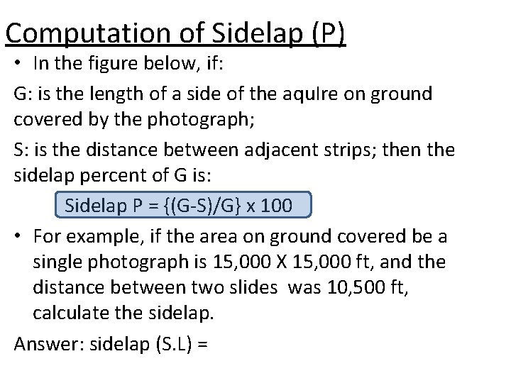
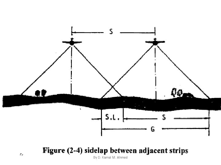
Computation of Sidelap (P) • In the figure below, if: G: is the length of a side of the aqu. Ire on ground covered by the photograph; S: is the distance between adjacent strips; then the sidelap percent of G is: Sidelap P = {(G-S)/G} x 100 • For example, if the area on ground covered be a single photograph is 15, 000 X 15, 000 ft, and the distance between two slides was 10, 500 ft, calculate the sidelap. Answer: sidelap (S. L) = {(15, 000 -10, 500)}/15, 000 = 30% By D. Kamal M. Ahmed
By D. Kamal M. Ahmed
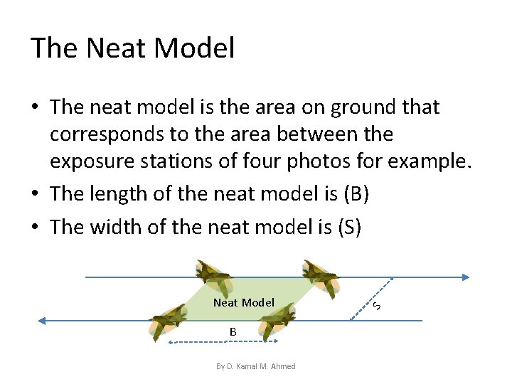
The Neat Model • The neat model is the area on ground that corresponds to the area between the exposure stations of four photos for example. • The length of the neat model is (B) • The width of the neat model is (S) Neat Model B By D. Kamal M. Ahmed S
3 - Purpose • The camera should be selected to serve the purpose of the survey best, one important factor is the angular field of view. • Field of view of the camera is controlled by the focal length of the camera and the size of the frame. The most commonly used aerial camera is 6 inch focal length and 9 inch X 9 inch frame By D. Kamal M. Ahmed
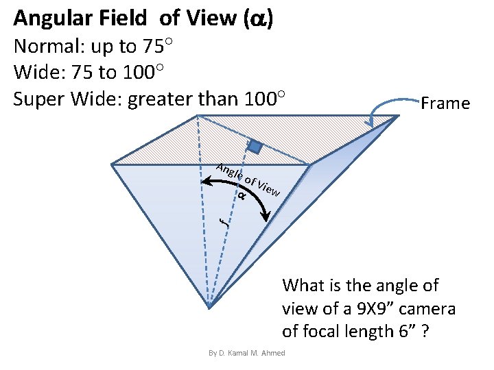
Angular Field of View ( ) Normal: up to 75 Wide: 75 to 100 Super Wide: greater than 100 Ang le o f Vi ew f Frame What is the angle of view of a 9 X 9” camera of focal length 6” ? By D. Kamal M. Ahmed
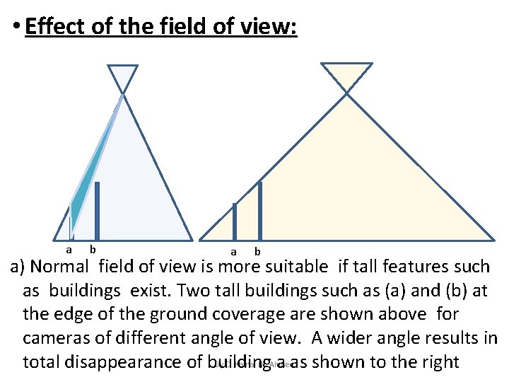
• Effect of the field of view: a b a) Normal field of view is more suitable if tall features such as buildings exist. Two tall buildings such as (a) and (b) at the edge of the ground coverage are shown above for cameras of different angle of view. A wider angle results in By D. Kamal M. Ahmed total disappearance of building a as shown to the right
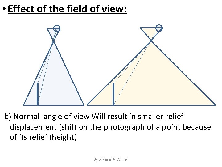
• Effect of the field of view: b) Normal angle of view Will result in smaller relief displacement (shift on the photograph of a point because of its relief (height) By D. Kamal M. Ahmed
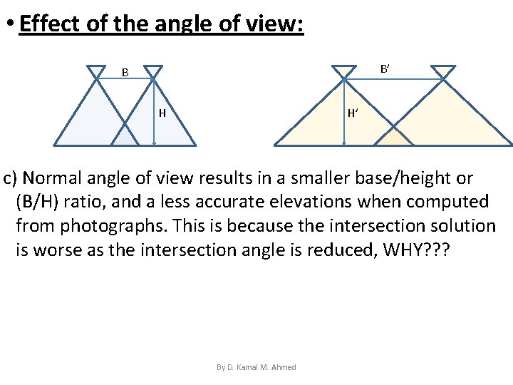
• Effect of the angle of view: B’ B H H’ c) Normal angle of view results in a smaller base/height or (B/H) ratio, and a less accurate elevations when computed from photographs. This is because the intersection solution is worse as the intersection angle is reduced, WHY? ? ? By D. Kamal M. Ahmed
• Effect of the angle of view: In summary • For generating contours, you need better elevation values, you need a larger base to height ratio, you need a wider filed of view (topographic mapping) • For interpretation or reconnaissance purposes, you need to see as much as you can, less features obscured by others and less effect of relief, you need a camera with smaller field of view By D. Kamal M. Ahmed
4 - Scale The scale of photographs is also determined according to purpose: • for interpretation purposes, you need to see features bigger, you chose a larger scale • for topographic mapping purposes, usually five times enlargement form photo to map scale is preferred. For example, Engineering maps at the scale of 1: 500 are often produced from 1: 3, 000 scale aerial photography using an enlargement ratio of 6. By D. Kamal M. Ahmed
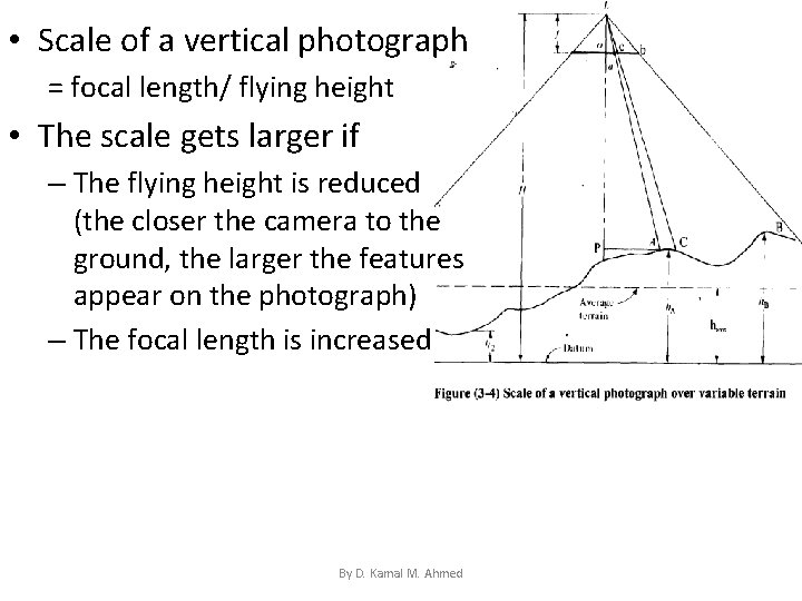
• Scale of a vertical photograph = focal length/ flying height • The scale gets larger if – The flying height is reduced (the closer the camera to the ground, the larger the features appear on the photograph) – The focal length is increased By D. Kamal M. Ahmed
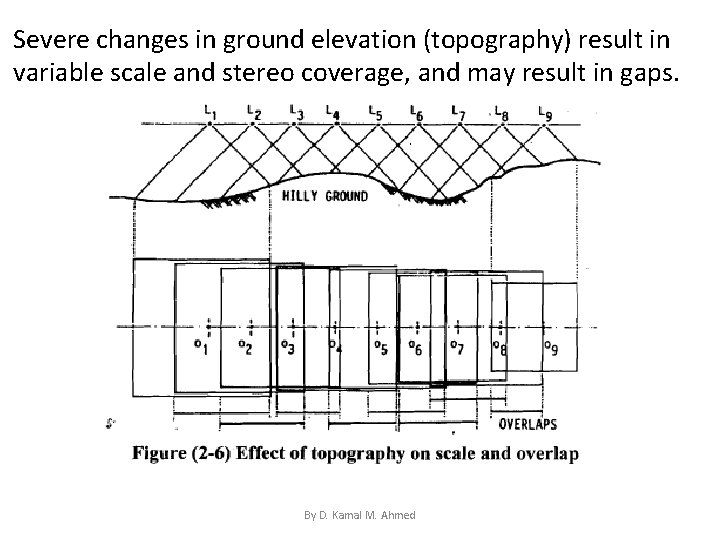
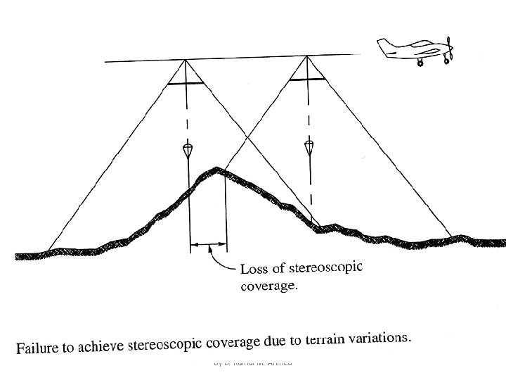
Severe changes in ground elevation (topography) result in variable scale and stereo coverage, and may result in gaps. By D. Kamal M. Ahmed
By D. Kamal M. Ahmed
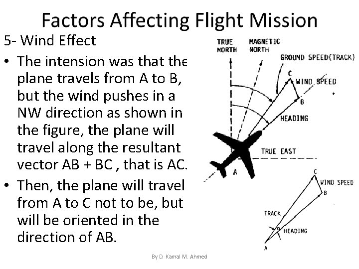
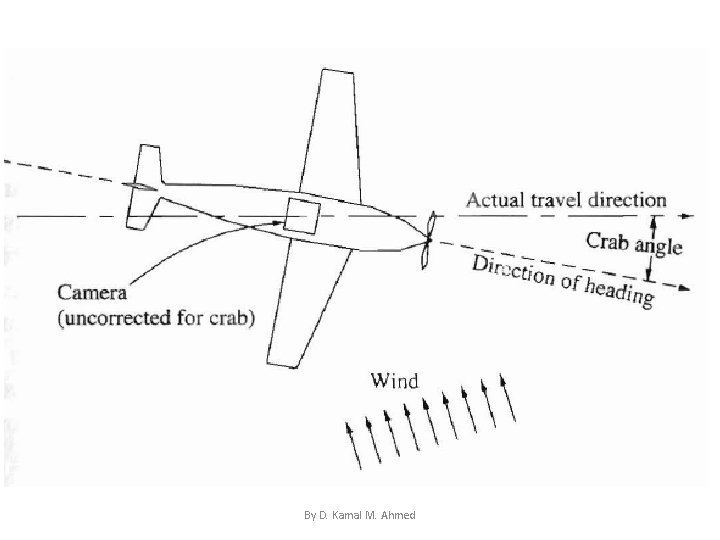
5 - Wind Effect • The intension was that the plane travels from A to B, but the wind pushes in a NW direction as shown in the figure, the plane will travel along the resultant vector AB + BC , that is AC. • Then, the plane will travel from A to C not to be, but will be oriented in the direction of AB. By D. Kamal M. Ahmed
By D. Kamal M. Ahmed
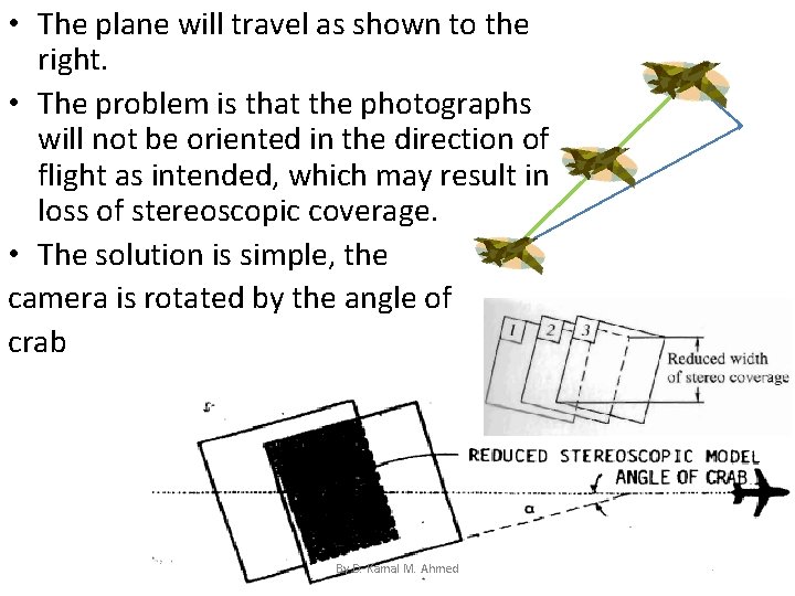
• The plane will travel as shown to the right. • The problem is that the photographs will not be oriented in the direction of flight as intended, which may result in loss of stereoscopic coverage. • The solution is simple, the camera is rotated by the angle of crab By D. Kamal M. Ahmed
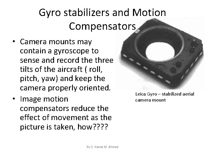
Gyro stabilizers and Motion Compensators • Camera mounts may contain a gyroscope to sense and record the three tilts of the aircraft ( roll, pitch, yaw) and keep the camera properly oriented. • Image motion compensators reduce the effect of movement as the picture is taken, how? ? By D. Kamal M. Ahmed Leica Gyro – stabilized aerial camera mount
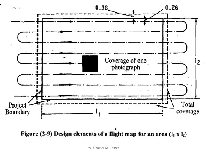
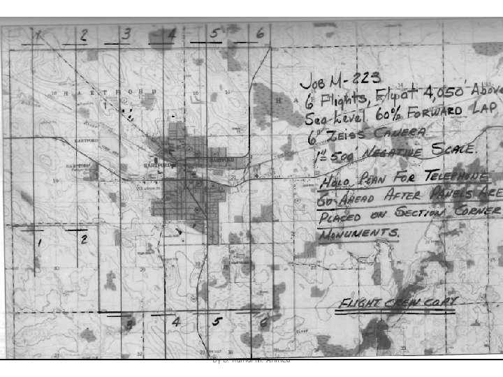
Design of Flight Map • A flight map is a map ( or a photograph in absence of a map) to guide the mission, it should show, to scale: 1. Boundaries of the area to be covered (photographed): usually extended by about 30% G at each of the sides 2. Direction of flight lines (strips) : usually selected in the direction of long side of the area covered 3. Location of each exposure station: determined according to the length of the strip and endlap. By D. Kamal M. Ahmed
By D. Kamal M. Ahmed
By D. Kamal M. Ahmed
Design of Flight Map • Flight plan is shown on a map to show flying lines (location, start, and end), and the location at which each photograph is to be taken (location of exposure station). • Given the dimensions of ground coverage and the percent of end and side lap (R and P %), you should be able to compute the number of strips and the number of photographs to be taken. By D. Kamal M. Ahmed
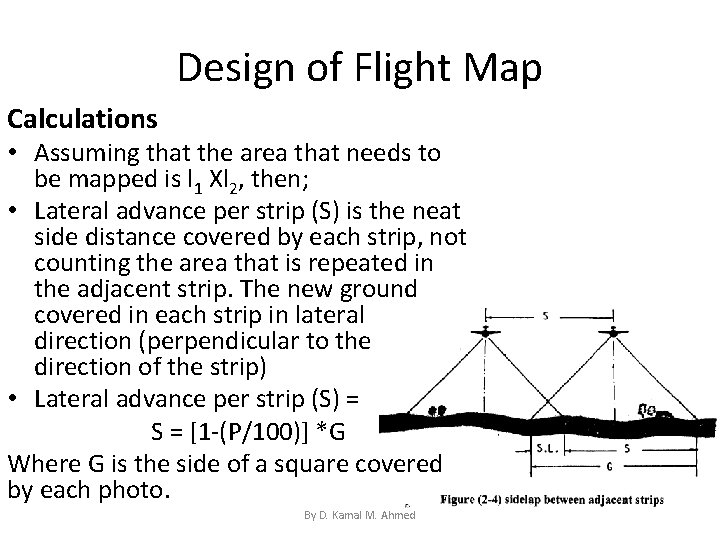
Design of Flight Map Calculations • Assuming that the area that needs to be mapped is l 1 Xl 2, then; • Lateral advance per strip (S) is the neat side distance covered by each strip, not counting the area that is repeated in the adjacent strip. The new ground covered in each strip in lateral direction (perpendicular to the direction of the strip) • Lateral advance per strip (S) = S = [1 -(P/100)] *G Where G is the side of a square covered by each photo. By D. Kamal M. Ahmed
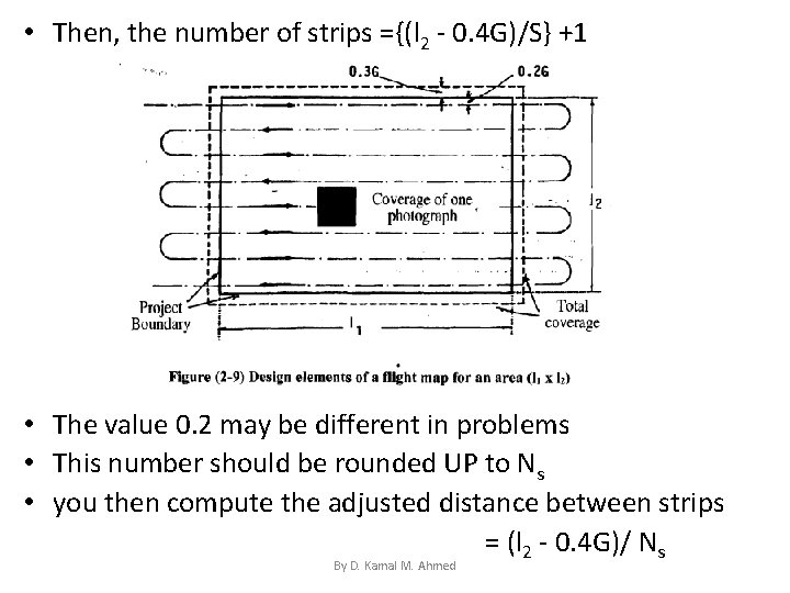
• Then, the number of strips ={(l 2 - 0. 4 G)/S} +1 • The value 0. 2 may be different in problems • This number should be rounded UP to Ns • you then compute the adjusted distance between strips = (l 2 - 0. 4 G)/ Ns By D. Kamal M. Ahmed
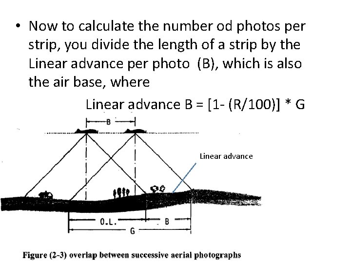
• Now to calculate the number od photos per strip, you divide the length of a strip by the Linear advance per photo (B), which is also the air base, where Linear advance B = [1 - (R/100)] * G Linear advance By D. Kamal M. Ahmed
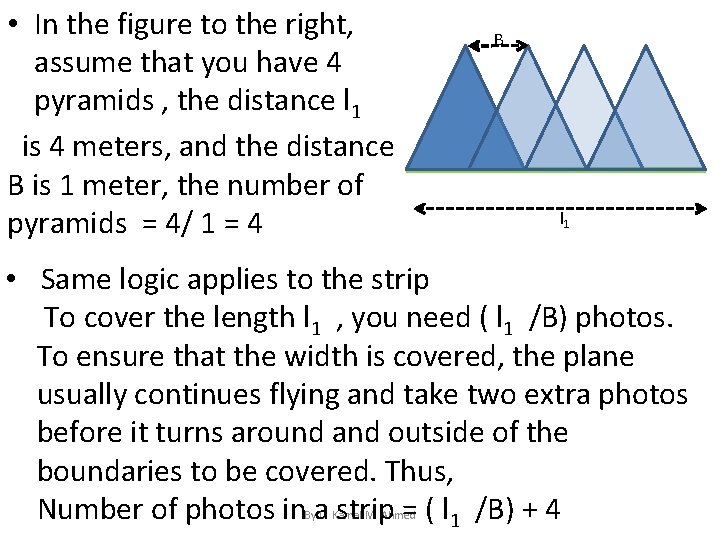
• In the figure to the right, assume that you have 4 pyramids , the distance l 1 is 4 meters, and the distance B is 1 meter, the number of pyramids = 4/ 1 = 4 B l 1 • Same logic applies to the strip To cover the length l 1 , you need ( l 1 /B) photos. To ensure that the width is covered, the plane usually continues flying and take two extra photos before it turns around and outside of the boundaries to be covered. Thus, Number of photos in a strip = ( l 1 /B) + 4 By D. Kamal M. Ahmed
Design of Flight Map • Example 2 -1 Calculate the total number of photographs needed to be taken by a standard camera to map an area that is 12 X 8. 5 miles, the average scale of the photographs is 1: 15, 000, overlap and sidelap are 60% and 25% respectively. Answer: G = 9 X 15, 000/12 = 11, 250 ft By D. Kamal M. Ahmed
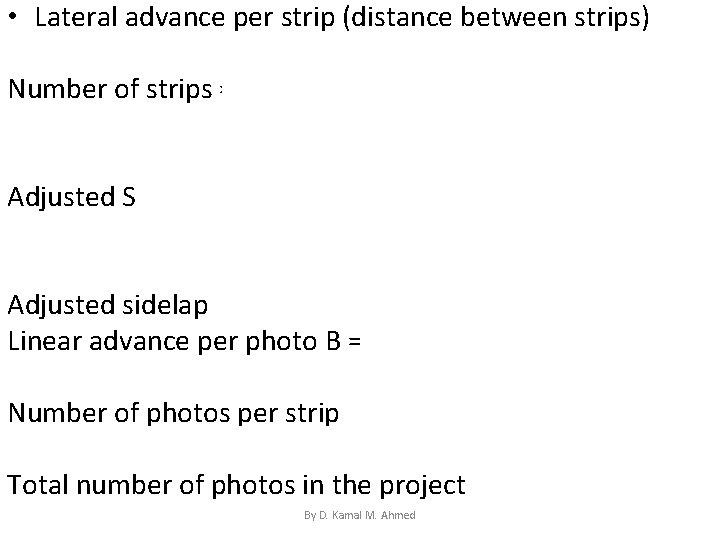
• Lateral advance per strip (distance between strips) S = [1 - (25/100)) * 11, 250 = 8437. 5 ft Number of strips =[ (8. 5*5, 280) – (0. 4 *11, 250)] +1 8437. 5 =5. 79 strips, assume 6 strips Adjusted S = [ (8. 5*5, 280) – (0. 4 *11, 250)] 5 = 8076 ft Adjusted sidelap =[(G-S)/G] *100 = 28. 2% Linear advance per photo B = [1 -(60/100)] *11, 250 =4500 ft Number of photos per strip = [12*5, 280/4500] +4 = 18. 08 Assume number of photos per strip is 19, then Total number of photos in the project = 19*6 = 114 photos By D. Kamal M. Ahmed
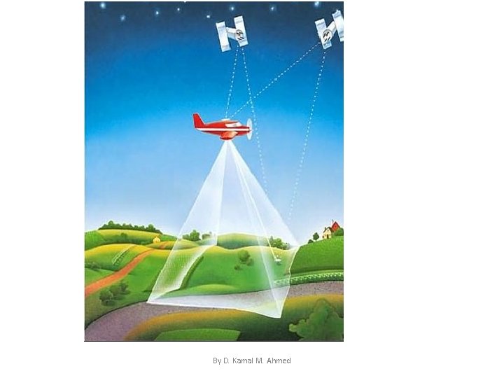
Airborne GPS • Airborne GPS is used to measure the location of the camera at the instant of exposure. This gives the photogrammetrist XL, YL, and ZL. GPS can also be used to derive the orientation angles by using multiple antennas. Unfortunately, the derived angular relationships only have a precision of about 1’ of arc while photogrammetrists need to obtain these values to better than 10” of arc. • To compute the position of the camera during the project, two geodetic GPS receivers are commonly employed. One is placed over a point whose location is known and the other is mounted on the aircraft. Carrier phase data are collected by both receivers during the flight with sampling rates generally at either 0. 5 or 1 second. Generally, on-thefly integer ambiguity resolution techniques are employed. By D. Kamal M. Ahmed
By D. Kamal M. Ahmed
ADVANTAGES OF AIRBORNE GPS • The main limitation of photogrammetry is the need to obtain ground control to fix the exterior orientation elements (three rotations of the photo around the three axes, and three coordinates of exposure station L). The necessity of obtaining ground control is costly and time-consuming. • GPS gives the photogrammetrist the opportunity to minimize (or even eliminate) the amount of ground control and still maintain the accuracy needed for a mapping project.
Flight Planning for Airborne GPS When planning for an airborne GPS project, special consideration must be taken into account for the addition of the GPS receivers that will be used to record the location of the camera. The first issue is the form of initialization of the receiver to fix the integer ambiguities. Next, when planning the flight lines, the potential loss of lock on the satellites has to be accounted for. Depending on the location of the airborne receiver, wide banking turns by the pilot may result is a loss of the GPS signal. Banking angles of 25° or less are recommended which results in longer flight lines
• The location of the base receiver must also be considered during the planning. Will it be at the airport or near the job site? The longer the distance between the base receiver and the rover on the plane the more uncertain will be the positioning results. • When planning, try to find those times when the satellite coverage consists of 6 or more satellites with minimum change in coverage • Also plan for a PDOP that is less than 6 to ensure optimal geometry. Additionally, one might have to arrive at a compromise between favorable sun angle and favorable satellite availability. • Make sure that the GPS receiver has enough memory to store the satellite data. • There may also be some consideration on the amount of sidelap and overlap when the camera is locked down during the flight. This will be important when a combined GPS-INS system is used. • Finally, a flight management system should be used to precalculate the exposure station locations during the flight
GPS-Aided Navigation • One of the exciting applications of airborne. GPS is its utilization of in flight navigation. • The ability to precisely locate the exposure station and activate the shutter at a predetermined interval along the flight line is beneficial for centering the photography over a geographic region.
- Slides: 54