Philosophy of Building CN 2 Xu Jianfeng China

Philosophy of Building CN 2 Xu Jianfeng China Telecom Corporation http: //www. chinatelecom. cn

Background Challenges Total voice traffic and revenue decreases by the end of 2005. The mobile phone and IP phone calls have cannibalized part of the voice traffic businesses Traditional communication network is unable to support China Telecom’s strategy to become a Comprehensive Information Service Provider. This is due to its lack of capability in offering value-added service and service awareness on a unified network. High OPEX (Operating Expenses) is required for operating separate networks in a tradition way The existing China. Net is not best choice for NGN, 3 G, VPN and other strict SLA demanding services Opportunities Acceleration of the Information and Communications Technology (ICT) adoption in government and enterprises would drives the demand for telecom services Adoption of the SIP-based soft-switch technology The impending releases of 3 G license Rapid development of the broadband service Fix and Mobile Convergence ( FMC )

Solutions Migration of voice service from PSTN network to IP-based network Preparation for 3 G-based mobile services Accelerate the development and deployment of the broadband services base on x. DSL access technology Drive managed service and system integration service Triple play services and future IP NGN convergence including network convergence, service convergence and application convergence Built an Integrated IP/MPLS-based multi-service platform — CN 2:China telecom Next Carrier Network

Philosophy of Building CN 2 Simple network topology Scalable routing architecture Highest level of redundancy Highest level of security Different class service Day one support for voice , video and data End to end control and management
 ISIS level 2 -only")
CN 2 Strength Homogeneous Global Architecture Single Global ASN(AS 4809) ISIS level 2 -only with sub-second convergence MPLS FRR with sub-50 ms reroute Robust Architecture Allows for Unsurpassed Stability Diffserv-based QOS、MPLS and multicast enabled network 6 PE-based IPV 6 network Offer Layer-2/3 public/private flexible connectivity over IP or MPLS Leading SLAs via Zero Loss & Speed of Light Delays Fast automated end to end service provision and fault management utilizing industry leading IP service management solutions, help to greatly reduced OPEX and accelerate service deployment End to end IP SLA monitoring tool make CN 2 a true carrier class network

Simple Network Topology CN 2 comprises of two functional planes and four structural layers to offer a seamless connectivity for customers. The two functional planes are high speed data forwarding plane and service provisioning plane The four structural layers are core layer, aggregation layer, edge layer and services connecting layer The high speed data forwarding plane and service offering plane is supported by 4 and 1 vendors respectively. This is to ensure minimum service disruption and better edge services control. SR/PE Service Edge Aggregation SR/PE Core 高速转发层 业务接入层 SR/PE
 IP/MPLS Network All-Optical,Dense Wave Division Multiplexing (DWDM) SONET/SDH framing Per flow")
Simple Network Topology(cont) IP/MPLS Network All-Optical,Dense Wave Division Multiplexing (DWDM) SONET/SDH framing Per flow load-sharing and failover load-sharing with ISIS MPLS is enabled on all network with VPN traffic encapsulated in MPLS and others transported in native IP IP IP MPLS SONET FRAMING DWDM

Scalable route architecture To ensure network’s scalability and security, only infrastructure address blocks are redistributed into the IS-IS (IGP) routing table. Non-infrastructure addresses are redistributed in BGP. Keeping the IS-IS routing table to a minimum would greatly enhance the network stability. Single Global ASN (AS 4809) BGP Communities are deployed for routes control and netflow-based traffic monitor CN 2 have two type Route reflector VPN RR for RFC 2547 -based VPN service, (VRR) Global RR for global internet routing(GRR) VPN RR is independent of global RR, both use one level Route Reflector(RR) Global i. BGP: Scaling the Global Internet Routing Table involve the increase in the number of GRR group, each group handles a part of global routes. VPN i. BGP: Likewise, scaling the VPN routing Table involve the increase of VRR group. Example, VPN 1 -500 is handled by VRR-G 1 while VPN 501 -1000 can be handled by VRR-G 2
 Scaling the Global Internet Routing Table Group 1 for part")
Scalable routing architecture (Cont) Scaling the Global Internet Routing Table Group 1 for part 1 routes Group 2 for Part 2 routes Full mesh Peers GRR 1 GRR 2 Full mesh Peers GRR 3 Send Part 1 routes to G 1 Send Part 2 routes to G 2 Client EBGP Internet GRR 4 Client Receive Part 1 routes from G 1 Client Receive Part 2 routes from G 2 EBGP Internet
 scaling the VPN routing Table Group 1 for VPN 1")
Scalable route architecture (Cont) scaling the VPN routing Table Group 1 for VPN 1 -500 routes Group 2 for VPN 501 -1000 routes Full mesh Peers VRR 1 VRR 2 VRR 3 VRR 4 Send/ receive VPN 1 routes to/from G 1 Send/ receive VPN 501 routes to/from G 2 Client PE PE PE

Highest Level of redundancy All network links are deployed in pairs over diverse facilities Only POS interface are used on backbone link to do faster link failures detection All network links are active (NOT working and protect) Each Po. P’s router pair is connected by multiple routers. Link failure protection is done through IS-IS (layer 3 control) and not dependent on transport layer (layer 2 control) IS-IS routing protocol Per flow load sharing between dual pairs Fail-over load sharing Sub-second fast convergence for gold service Three priority LSP flooding and FIB update MPLS FRR 1: 1 mode FRR is deployed in core layer for 50 links Sub-50 ms reroute time Built to maintain utilization not to exceed 50% during normal running As a congestion-free network, CN 2 ensures premium priority for delivery of all packets in the core

Higher Level of security Strict u. RPF is deployed on all customer access interfaces Loose u. RPF is deployed on interconnected interface Infrastructure ACLs (i. ACL) deny external traffic to ALL routers interfaces address. i. ACL are deployed on edges and borders of the network. No one outside network can reach routers Infrastructure routes are not distributed to internet or customer All router access control is managed by AAA servers and syslog QOS technology would be deployed accordingly to reduce the impact of an attack or worm traffic. All customer facing routers interfaces do not have IGP turn on. When EBGP are deployed on these interfaces, BGP MD 5 hash must be configured

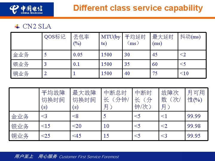
Differentiated class service capability CN 2 Qo. S positioning Qo. S is used to allocate limited network resources to different services. Unlike traditional networks of ATM, Frame Relay, and lease circuit services, CN 2 provides an uniform network for all these services. To differentiate the services based on the class of importance or contract, Qd. S is the mechanism in place to segregate and allocate network resources to different class of services. Example of a Qo. S policy: 3 G and soft-switch traffic can be allocated with at least 50% of the available bandwidth while Vnet can only consume a maximum of 15% of the total bandwidth Qo. S are also positioned for traffic congestion management. Under the accidental circumstances of equipment or circuit failures, Qo. S helps to manage the limited usable network resources to different classes of services. Better resource utilization is expected from deploying Qo. S. Having elastic policy to re-allocate the under-utilized resources results in efficient resources utilization.
 Qo. S design philosophy CN 2 adhere to Diff.")
Differentiated class service capability (Cont) Qo. S design philosophy CN 2 adhere to Diff. Serv framework based on IP precedence and MPLS EXP Bit classification. Thus offering 8 classes of service Initial CN 2 service classification is base on 5 basic classes of services. 1 class for network control traffic 1 class for CT internal service 3 classes for service offering All services are classified, remarked, shaped and rate-limited on the edge of the network to ensure a consistent QOS policy enforcement within the CN 2 network Service resource allocation is based on class of service. GOLD class of service would be allocated with 2 times more redundant resources than BRONZE class of service Convergence of prefix varies on the traffic class. Prefixes of a GOLD class of traffic would converge faster than prefixes of BRONZE class of traffic

All services are Edge Functions Services are enforced and policed on the edges of the network via the SR/PE device. Service comprises of soft-switch, video conference, VPN, Internet, ATM/FR/DDN etc. To ensure core network’s stability and security, service provisioning, new service deployment and security control are performed on the edge of the network. . The SOLE responsibility of the Core Network is packet switching and forwarding QOS edge Corporate Dial PE PE broadband access PE PE PE MPLS L 3 VPN P PE IPSec VPN PE P P P IP/MPLS platform P SDH/DD PE P PE ATM/FR PE P P PE Integrated VPN MPLS L 2 VPN PE PE Ao. MPLS
: CN 2 will provide coverage")
Network Capacity and Coverage (by the end of 2005): CN 2 will provide coverage for 208 cities including Hong Kong, Tokyo, Singapore, London, New York, San Jose, Washington etc. with service offering MPLS/VPN and Internet Services. 671 routers in total,including 439 P routers,208 PE/SR routers,12 Public RR,and 12 VPN RR 1267 relay links with a total link bandwidth of 4. 231 T Over 800 external interlinkage with a total bandwidth of 2. 8 T A total customer access link bandwidth of 650. 62 G CN 2 uses Cisco 12416 with E 3&SIP line cards as PE routers exclusively to ensure a consistent connectivity and configuration management. This would reduce equipment interoperation issue as well as the speed of problem resolution.
 Ethernet")
CN 2 service capability Support MPLS layer 2/3 VPN L 3 VPN(RFC 2547) Ethernet point to point service(Draft-martini) Ethernet multi point service (Vkompella VPLS) ATM/FR over MPLS Support 3 classes of service. GOLD, SILVER and BRONZE. Support internet & VPN services with SDH、Ethernet/VLAN、 ATM/FR/DDN、 L 2 TPv 3, pseudo-wired access Support network wide multicasts of 600 groups, 1. 2 Gbps end to end multicast traffic Support network wide 6 PE-based IPv 6 with wire speed CN 2 uses Cisco 12416 with E 3&SIP line cards as PE routers exclusively to ensure a consistent connectivity and configuration management. This would reduce equipment interoperation issue as well as the time of problem resolution, thus be more agile in time to market.

- Slides: 19