Persistence of Vision LED Sphere Display Group 26


 • Slip")


 Hall Effect Sensor(Vertical) LED Data (SPI) LED Clock(SPI)")


 to receive signal from Hall Sensor •")
{ attach. Interrupt(0, h_magnet_detect, FALLING);")

{ Fast. LED.")


- Slides: 37
Persistence of Vision LED Sphere Display Group 26 Michael Ling Lunan Li Jiale Quan
Introduction ● A Spinning Ring of LEDs Capable of Creating a Persistence of Vision (POV) Effect at 24 Frames Per Second (FPS) ● A Visually Appealing and Entertaining Way to Display Images and Animations ● Potential New Digital Marketing Method
System Overview • Mechanical • Custom-Built LED Ring Stand (ECE Machine Shop) • Slip Rings • DC Motors • Hardware • Microcontroller • Motor control circuit • 8 -Bit RGB LEDs • Software • 2 DOF Algorithm • GUI
The POV LED Sphere System LED Ring Motor Driving LED Ring Slip Ring Spinning Plate
The POV LED Sphere System TIP Transistors Microcontroller PCB Slip Ring Motor Driving Spinning Plate
System Overview
Mechanical Overview • Custom Design LED Ring Stand • Two Degrees of Freedom • Stable Enough for High RPM LED Ring • Manufactured by the ECE Machine Shop (David Switzer) Spinning Plate
Theoretical Torque Calculations
DC Motors • Necessary to Spin the LED Ring in Two Directions • 720 RPM for Spinning Plate • 30 RPM for LED Ring • 64 Counts Per Rotation Encoder (Not Used)
Slip Rings • Transfer Power and Data Between Stationary and Rotating Parts • Transmit 12 V to the LED Ring-Motor • Transmit 5 V to the LED Strip and Hall Sensors • Able to Transmit Data (Design Change) • Transmit Data to the LED Strip
Mechanical Achievements • Custom LED Ring Display Stand • Reliable Power and Data Transmission via Slip Rings • 30 RPM for LED Ring • 720 RPM for Spinning Plate
Future Mechanical Improvements • Drive the LED Ring Using a Stepper Motor • Slip Ring with 22 AWG Wires (instead of 28 AWG) • Redesign Mechanical Portion for Optimal Motor Placement
Hardware Overview ● Microcontroller ● TIP transistor ● LED ring ● Hall Effect Sensor
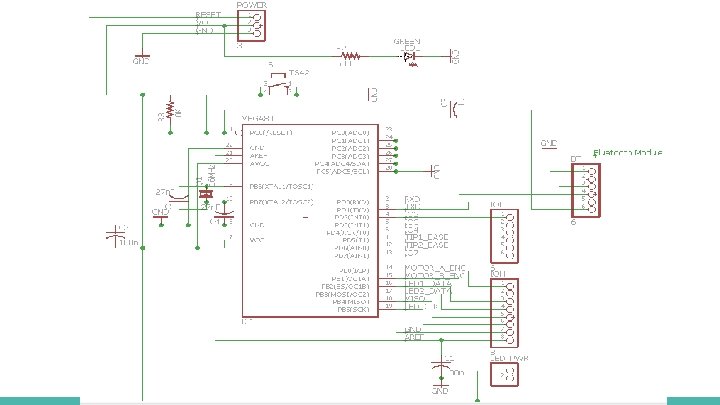
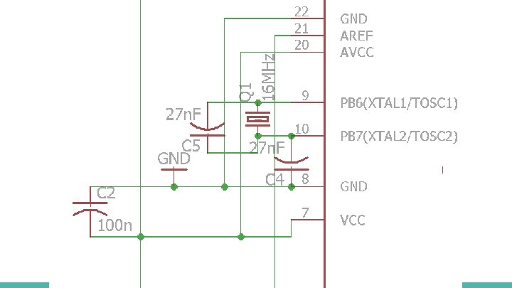
Microcontroller-Atmega 328 P Hall Effect Sensor(Horizontal) Hall Effect Sensor(Vertical) LED Data (SPI) LED Clock(SPI) TIP base (Horizontal) TIP base (Vertical)
RPM and Limitations ● Higher RPM will achieve higher FPS ● Higher RPM also has higher requirement for hardware ○ Data transmission ○ Safety issues while spinning Desired FPS Desired Spinning Plate RPM 12 (critical FPS to form POV effect) 360 24(optimal) 720 30(stabler and clearer) 900
Motor Control Circuit TIP 120 - NPN Epitaxial Darlington Transistor
LED Ring
Hall Effect Sensor • Using Hall Effect Sensor to measure the RPM Parameter Output North Pole High Null or weak magnetic field High South Pole Low • Indication of the starting point
Hardware Achievements
Hardware Future Improvement • Improve data transmission speed for LED Strip • Chip with higher frequency • LED Strip with multiple data lines
Software Overview • Magnet Interrupt • LED Strip programming • Two Degree of Freedom(2 DOF) Algorithm • User Input Interface
Magnet Interrupt • Use Arduino attach. Interrupt() to receive signal from Hall Sensor • attach. Interrupt(Pin, ISR, Mode); • Pin - Pin number on Arduino. Pin 2 or 3 for Arduino Uno • ISR - Special functions for interrupts • Mode - Defines when the interrupt should be triggered
Magnet Interrupt • Magnet. ino - example code void setup(){ attach. Interrupt(0, h_magnet_detect, FALLING); } void loop(){} void h_magnet_detect(){ LED_INDEX = 0; h_revolutions++; }
LED Strip Programming • Fast. LED • An Arduino library for programming addressable LED Strips • CRGB color groups • Refresh rate for Dot. Star APA 102 are 24 MHZ. We only achieve 8 MHZ due to hardware limitation. • Data Transmission cannot be interrupted
LED Strip Programming • fast. LED. ino - example code void setup(){ Fast. LED. add. Leds<APA 102, Data, Clock, RGB>(leds, NUM_LEDS); } void loop(){ for(int i = 0; i < NUM_LEDS; i++) leds[i] = CRGB: : Green; Fast. LED. show(); }
2 DOF Algorithm
Pseudocode for 2 DOF Algorithm • Set Up: • Set up Magnet Interrupts and LED Strips • Loop: • Calculate RPM and Refresh Rate for vertical/horizontal every five rotations • Check time for update. If yes, disable Interrupts and go to the next step. Other go back to Loop • Update LED properly • Enable Interrupts and go back to Loop
Hardware limitations in 2 DOF • Data Transmission cannot be interrupted • Interrupt may be blocked during Data Transmission • Inaccuracy for LED Positions • Microcontroller only sends data at 8 MHZ • Currently only refreshes LED Strip around 80 times in one rotation at 720 RPM • Our goal is to refresh around 600 times in one rotation at 720 RPM
User Input Interface • Allow users to customize display patterns
Software Achievements • Calculate RPM for both Horizontal and Vertical Direction • Display graphic patterns for both 1 DOF and 2 DOF • Display User Input Graphic Pattern
Future Software Improvements • Easy user input for UI • Allow users to type words or numbers • Translate them into graphic pattern
Results
Results
Credits David Switzer Vivian Hou Jackson Lenz Braedon Salz Ankit Jain Professor Kumar Professor Galvin
Questions?