
Periodic Structures and its Applications in Antennas Debabrata

Periodic Structures and its Applications in Antennas Debabrata Kumar Karmokar Student ID: 42660130 Principal Supervisor: Prof Karu Esselle Associate Supervisor: Prof Michael Heimlich Course: COMP 901 Academic Presentation and Writing Skills /19
Outlines: • • • What is a Periodic Structure? Importance of Periodic Structures What is a Leaky-Wave Antenna (LWA)? Physics of LWA Integration of Periodic Structures with Microstrip LWA (MLWA) Key Prior Research Aims and Expected Outcome Methodology Task Plan, Current Position, and Progress Conclusion Department of Engineering, Faculty of Science 2/19

What is a Periodic Structures? • Periodic structure is finite or infinite repetition of unit cells in one, two or three dimensions • Appear in nature in such forms as beehives, crystals, etc. Fig. 2. A finite beam on periodic simple supports (Mead D. J. , 1996) Fig. 1. A beehive (http: //oneida. uwex. edu/2011/06/30/building-beehive/) Fig. 3. Uniform planar PBG on microstrip substrate Fig. 4. Periodic stubs on a microstrip line (Pozar, D. M. , 2005 ) (Gupta, S. K. ) Department of Engineering, Faculty of Science 3/19
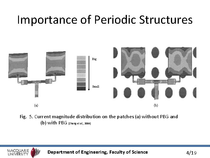
Importance of Periodic Structures Big Small (a) (b) Fig. 5. Current magnitude distribution on the patches (a) without PBG and (b) with PBG (Zhang et al. , 2004) Department of Engineering, Faculty of Science 4/19

What is a Leaky-Wave Antenna (LWA)? • LWA belong to the more general class of traveling wave antenna in which the guided wave gradually leaks out into the surrounding space to produce radiation • A wide-band microwave antenna that radiates a narrow beam whose direction varies with frequency + x Broadside Substrate Radiation Feed point - z Backfire Fig. 6. The earliest example of a leaky-wave antenna + y + z Endfire Microstrip line Ground Plane Fig. 7. Basic microstrip leaky-wave antenna (MLWA) (Oliner et al. , 1993) Department of Engineering, Faculty of Science 5/19
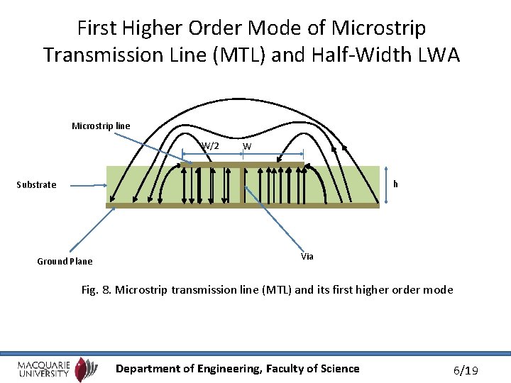
First Higher Order Mode of Microstrip Transmission Line (MTL) and Half-Width LWA Microstrip line W/2 W h Substrate Ground Plane Via Fig. 8. Microstrip transmission line (MTL) and its first higher order mode Department of Engineering, Faculty of Science 6/19
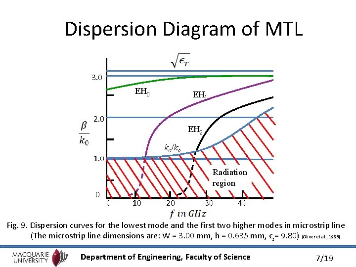
Dispersion Diagram of MTL 3. 0 EH 1 2. 0 EH 2 kc/ko 1. 0 Radiation region 0 0 10 20 30 40 Fig. 9. Dispersion curves for the lowest mode and the first two higher modes in microstrip line (The microstrip line dimensions are: W = 3. 00 mm, h = 0. 635 mm, ϵr= 9. 80) (Oliner et al. , 1986) Department of Engineering, Faculty of Science 7/19
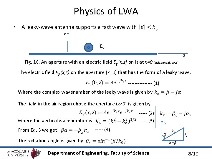
Physics of LWA • A leaky-wave antenna supports a fast wave with x Ey z Fig. 10. An aperture with an electric field Ey (x, z) on it at x=0 (Jackson et al. , 2008) The electric field Ey (x, z) on the aperture (x=0) that has the form of a leaky wave, -------- (1) Where the complex wavenumber of the leaky wave is given by The field in the air region above the aperture (x>0) is given by Where the vertical wavenumber is From Eq. 3 we get ----- (2) ----- (3) ----- (4) The radiation angle is given by Department of Engineering, Faculty of Science x θr k 0 kx kz=β 8/19
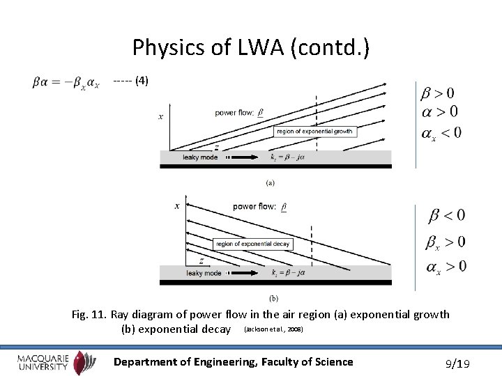
Physics of LWA (contd. ) ----- (4) Fig. 11. Ray diagram of power flow in the air region (a) exponential growth (b) exponential decay (Jackson et al. , 2008) Department of Engineering, Faculty of Science 9/19
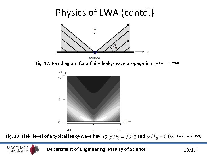
Physics of LWA (contd. ) Fig. 12. Ray diagram for a finite leaky-wave propagation Fig. 13. Field level of a typical leaky-wave having and Department of Engineering, Faculty of Science (Jackson et al. , 2008) 10/19
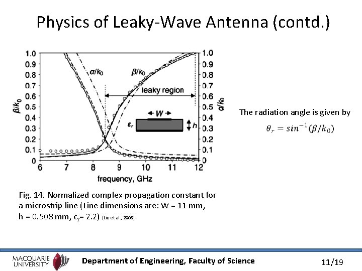
Physics of Leaky-Wave Antenna (contd. ) The radiation angle is given by Fig. 14. Normalized complex propagation constant for a microstrip line (Line dimensions are: W = 11 mm, h = 0. 508 mm, ϵr= 2. 2) (Liu et al. , 2008) Department of Engineering, Faculty of Science 11/19
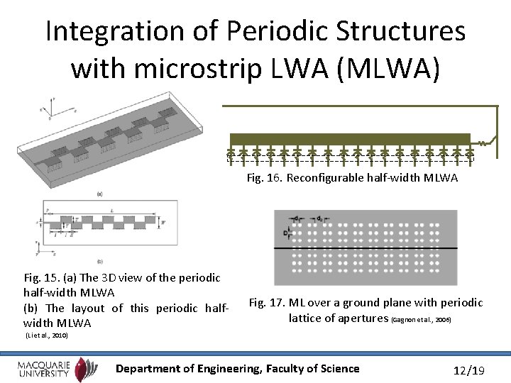
Integration of Periodic Structures with microstrip LWA (MLWA) Fig. 16. Reconfigurable half-width MLWA Fig. 15. (a) The 3 D view of the periodic half-width MLWA (b) The layout of this periodic halfwidth MLWA Fig. 17. ML over a ground plane with periodic lattice of apertures (Gagnon et al. , 2006) (Li et al. , 2010) Department of Engineering, Faculty of Science 12/19
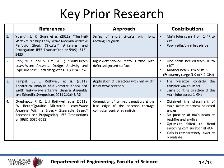
Key Prior Research References Approach Yuanxin, L. , X. Quan, et al. (2011). "The Half. Width Microstrip Leaky Wave Antenna With the Periodic Short Circuits. " Antennas and Propagation, IEEE Transactions on 59(9): 34213423. Series of short circuits with long rectangular guide • 2. Park, W. -Y. and S. Lim (2011). "Multi-Beam Leaky-Wave Antenna: Design, Analysis, and Experiments. " Electromagnetics 31(4): 247 -257 Right-/left-handed meta surface with defected ground surface • 3. Kempel, L. , E. Rothwell, et al. (2011). Theoretical analysis of a varactor-loaded halfwidth leaky-wave antenna. General Assembly and Scientific Symposium, 2011 XXXth URSI Application of varactors with half-width leaky-wave antenna • Ouedraogo, R. O. , E. J. Rothwell, et al. (2011). "A Reconfigurable Microstrip Leaky-Wave Antenna With a Broadly Steerable Beam. " Antennas and Propagation, IEEE Transactions on 59(8): 3080 -3083 Connection of lumped capacitors at the free edge of the antenna through computer controlled switch • 1. 4. Contributions • One beam steered from -80 to +100 • Another beam is fixed at 59 0 (Frequency range: 3. 9 to 4. 2 GHz) • • Department of Engineering, Faculty of Science Main lobe scans from 1440 to 410 Poor radiation in broadside The varactor controls the complex wavenumber Same pointing direction of the main lobe across 1 GHz Obtained the placement of main beam at several selected angles No position of main beam at backfire and endfire Optimizer failed to fiend switching configuration at -800 Gain is comparatively lower at broadside 13/19
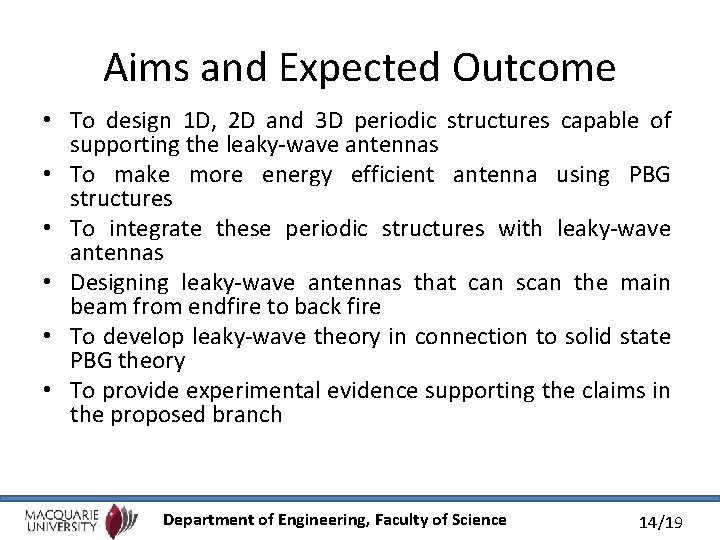
Aims and Expected Outcome • To design 1 D, 2 D and 3 D periodic structures capable of supporting the leaky-wave antennas • To make more energy efficient antenna using PBG structures • To integrate these periodic structures with leaky-wave antennas • Designing leaky-wave antennas that can scan the main beam from endfire to back fire • To develop leaky-wave theory in connection to solid state PBG theory • To provide experimental evidence supporting the claims in the proposed branch Department of Engineering, Faculty of Science 14/19
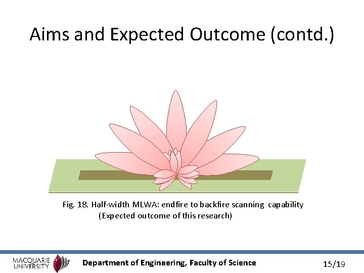
Aims and Expected Outcome (contd. ) Fig. 18. Half-width MLWA: endfire to backfire scanning capability (Expected outcome of this research) Department of Engineering, Faculty of Science 15/19
Methodology • Calculation of initial dimensions of the periodic structure • Mathematical modelling of the antenna system • Analysis of the modelled system • Optimization methods development • Observation of the electric current distribution • Study the effect of change in geometry of the periodic structures • Fabrication and testing of entire assembly • Post processing of measured and simulated results • Comparison of the simulated results with practical data Department of Engineering, Faculty of Science 16/19
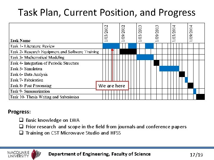
Task Plan, Current Position, and Progress We are here Progress: q Basic knowledge on LWA q Prior research and scope in the field from journals and conference papers q Training on CST Microwave Studio and HFSS Department of Engineering, Faculty of Science 17/19
Conclusion • • MLWA provide excellent properties Low profile, minimal weight, simple fabrication MLWA have wide range of applications Number of limitations in the previous research – Broadside scanning – Endfire and backfire scanning • Successful completion of this project should overcome most of the limitations • Development of a novel periodic leaky-wave antenna for continuous scanning from endfire to backfire through broadside Department of Engineering, Faculty of Science 18/19

Q & A Department of Engineering, Faculty of Science 19/19

Department of Engineering, Faculty of Science 20/19
- Slides: 20