Performance of Feedback Control Systems Test Input Signals

Performance of Feedback Control Systems

Test Input Signals:

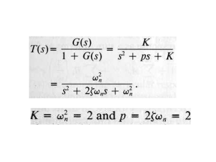
Performance of a Second Order System

Step Input:
 for a step input.")
Transient response of a second-order system (Eq. 5. 9) for a step input.
 for a step input")
The transient response of a second-order system (Eq. 5. 9) for a step input as a function of ζ and ωnt.

Impulse Input:

Response of a second-order system for an impulse function input.
.")
Step response of a control system (Eq. 5. 9).
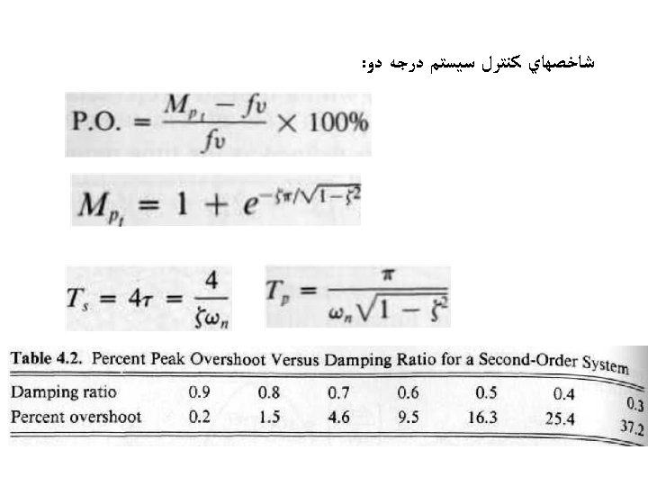

Percent overshoot and normalized peak time versus damping ratio z for a second-order system (Eq. 5. 8).

Normalized rise time Tr 1 versus ζ for a second-order system.

The step response for ζ = 0. 2 for ωn = 1 and ωn = 10.

Effect of the Third Pole on the 2 nd-Order System

An s-plane diagram of a third-order system.

Effect of the Zero on the 2 nd-Order System

Percent overshoot as a function of ζ and ωn when a second-order transfer function contains a zero.

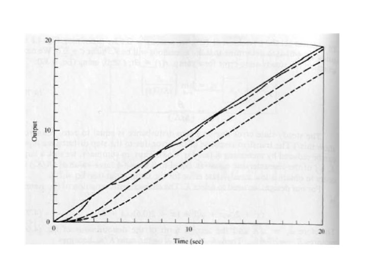
The response for the second-order transfer function with a zero for four values of the ratio (a/ζωn): A = 5, B = 2, C = 1, and D = 0. 5 when ζ =0. 45.

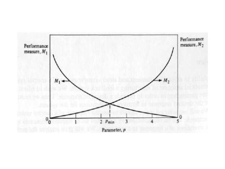
Examp. Ie 4. 1 Parameter Selection

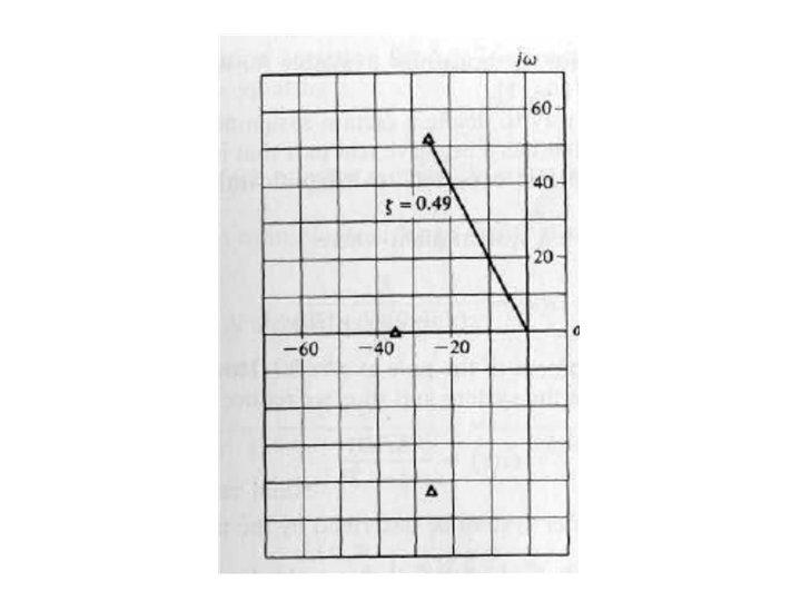
Specifications and root locations on the s-plane.

The s-Plane Root Location and the Transient Response

Impulse response for various root locations in the s-plane. (The conjugate root is not shown. )

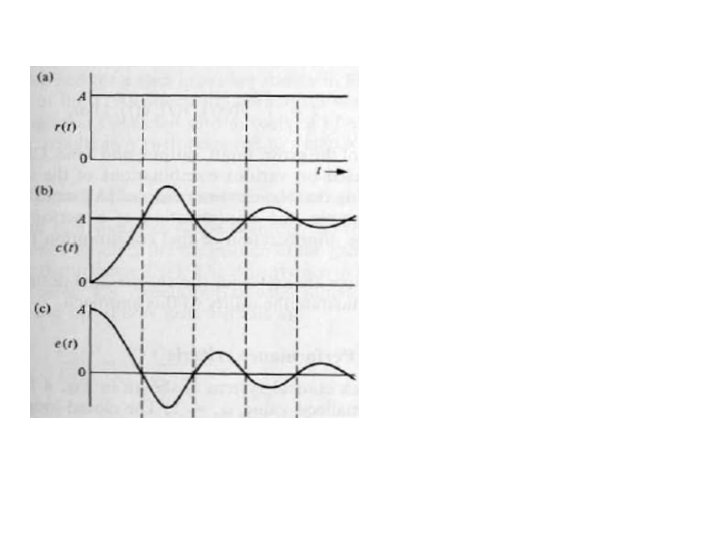
The Steady-State Error of Feedback Control Systems
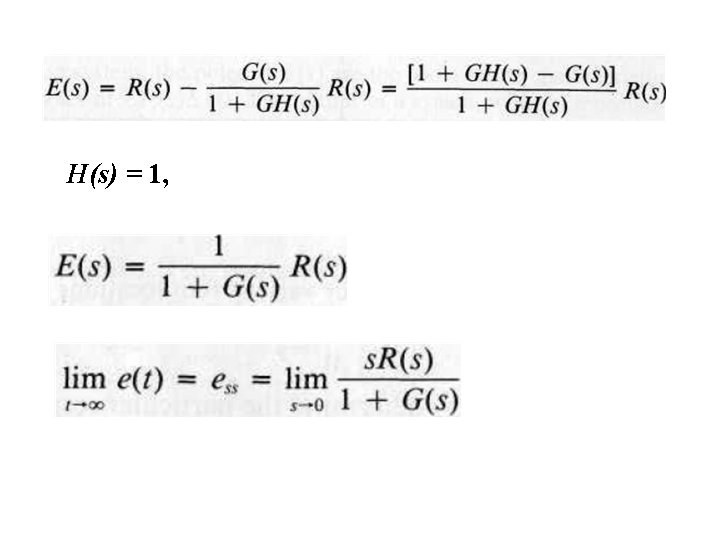

Step Input:

Step Input: N=0

Step Input: N>0

Ramp Input:

Ramp Input: K=1

Acceleration Input:

Acceleration Input: N=2


Triangular wave response.

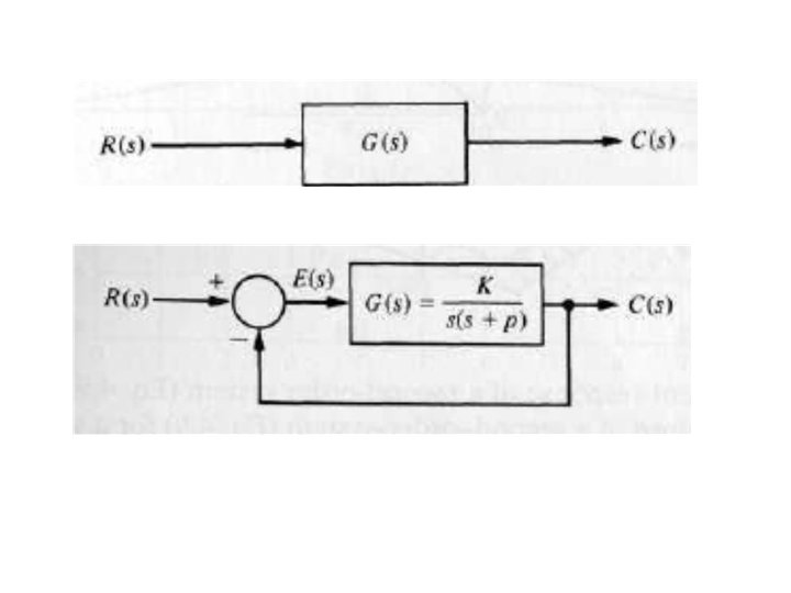
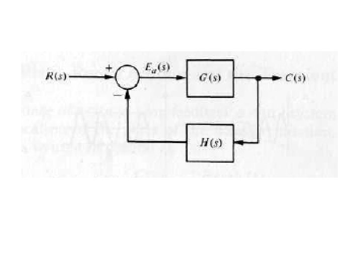
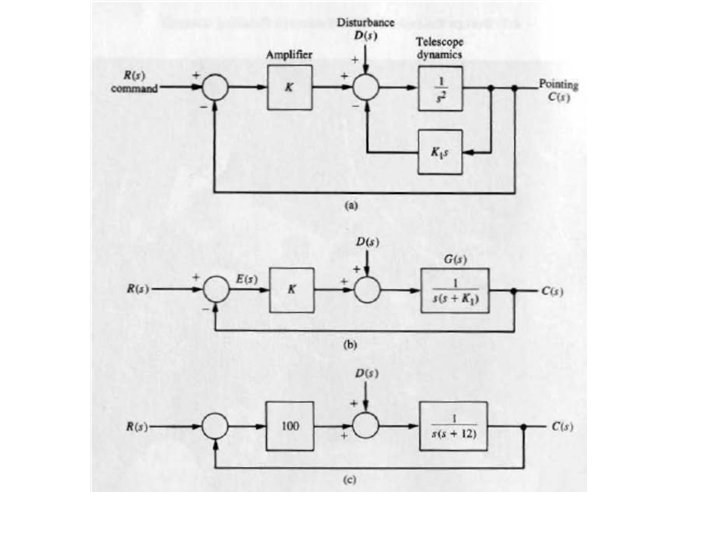
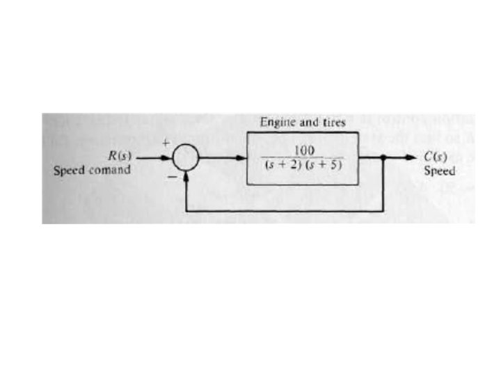
Control system model with a secondorder model of the motor and load.
 1, t (a) MATLAB")
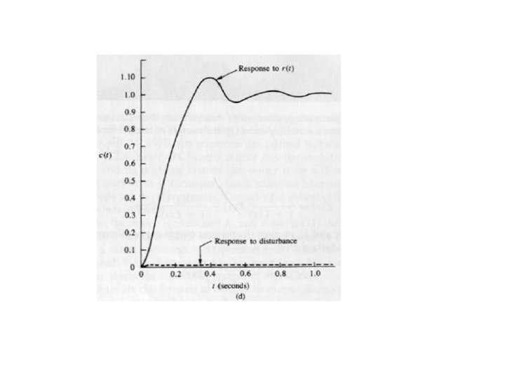
Response of the system to a unit step input, r(t) 1, t (a) MATLAB script.
 1, t (b) Response")
Response of the system to a unit step input, r(t) 1, t (b) Response for Ka 30 and 60.

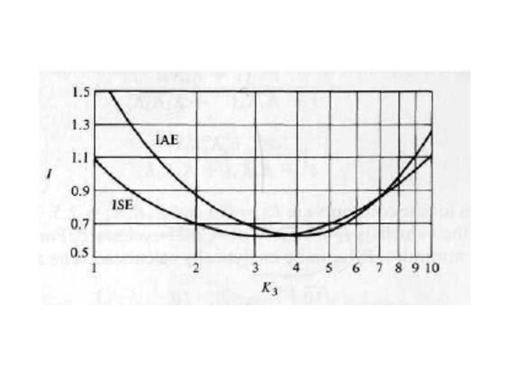
Performance Indices

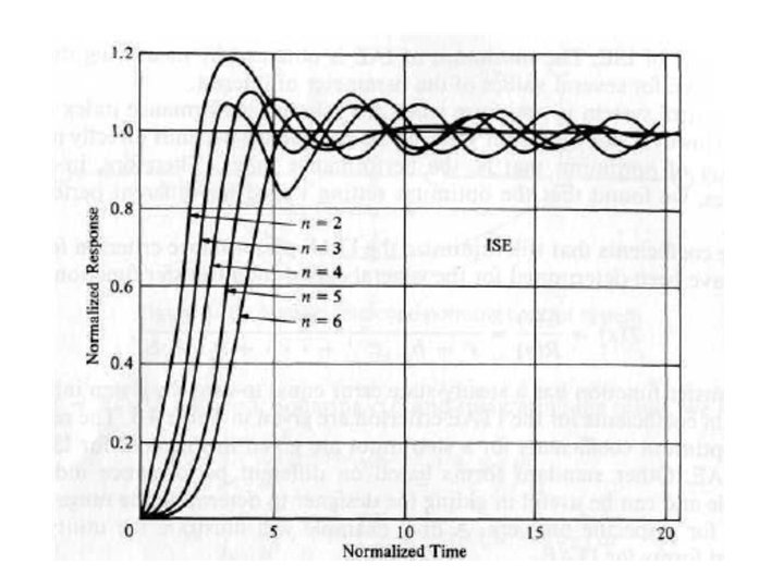
ISE: IAE: ITSE:

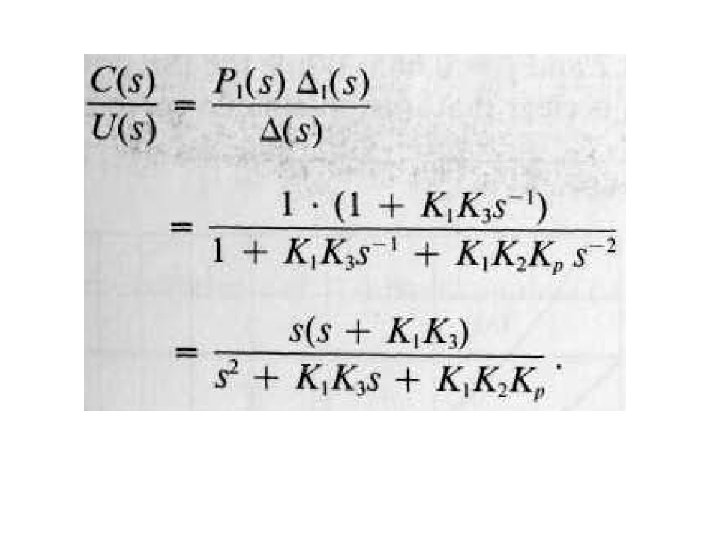
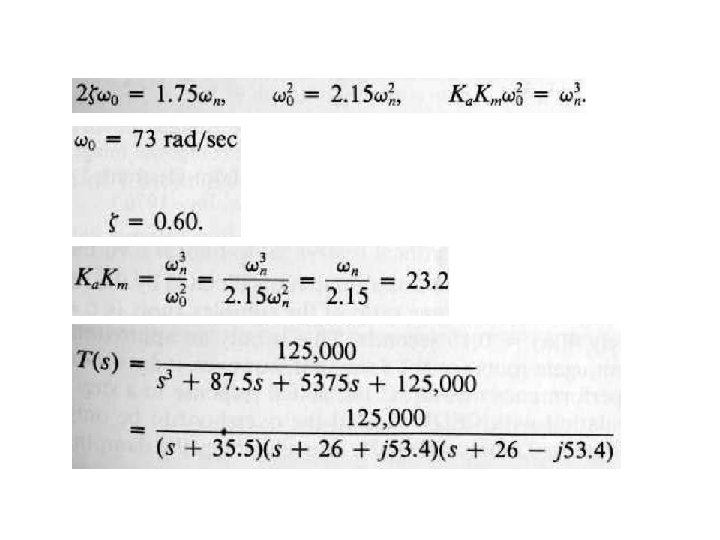
Example:
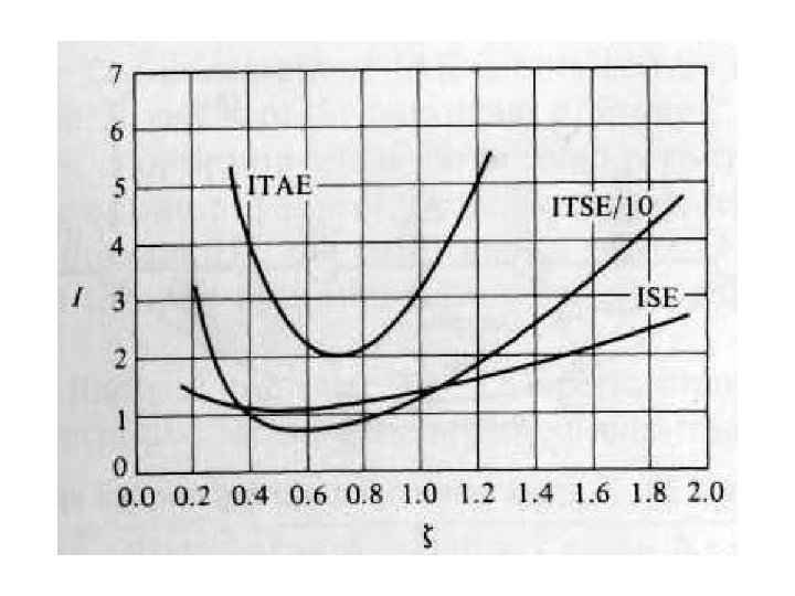

Example:
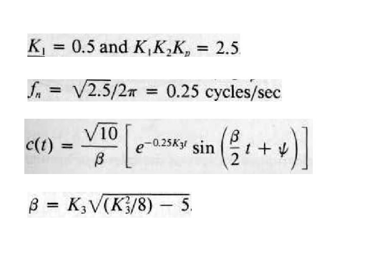
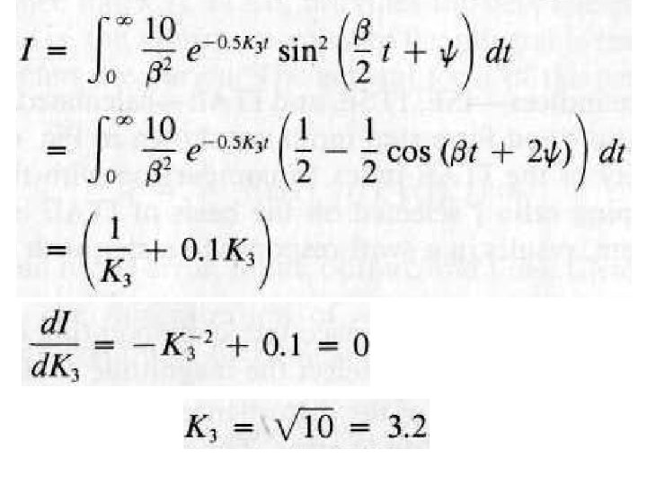

Step Response


Example:


- Slides: 71