PERFORMANCE ENHANCEMENT OF OPEN LOOP GAS RECOVARY PROCESS


 and TIFR")


 Separation od Carbon dioxide and Methane in continuous countercurrent")
 , India for analysis • Mr.")
- Slides: 27
PERFORMANCE ENHANCEMENT OF OPEN LOOP GAS RECOVARY PROCESS BY CENTRIFUGAL SEPARATION OF GASES Avinash V. Joshi(1) , Suresh D. Kalmani (2) Dr. P. V. Hunagund (3) (1) Alpha Pneumatics Thane (India) alpha. pneumatics@gmail. com (2) DHEP , TIFR Mumbai (India) (3) Dept. of Applied Electronics , Gulbarga University , Gulbarga ( India)
Alpha Pneumatics Product Range • • • 32 open ended gas mixing systems 3 close loop systems ( 2 with humidity control) 2 open loop system 7 pressure balance systems for thin detectors/windows Hodoscope Leak test system ( absolute pressure) for bakelite and glass gaps Gas handling and safety equipment Lead lined X ray cubicle with XYZ positioner for Large area GEM testing 1 m x 1 m and 1 m X 2 m Bakelite gaps DLC deposition systems
Activities of Alpha Pneumatics Pilot Close Loop System for 2 m. X 2 m Glass RPCs Close loop system for CMS RPC testing at Chandigarh India 1 m x 1 m bakelite gap in assembly Pressure Balance flow system for Thin Film Detectors
GEM related work Reactive Ion Etching of copper at 2. 0 W/sqcm , 90: 10 ratio of SF 6: O 2 and 60 min. Etch depth is 0. 5 microns. Reactive Ion Etching of Kapton at 20: 80 SF 6: O 2 ratio, 2 W/cm 2 power at 13. 56 MHz. After 60 min Etch depth is 24 microns.
Gas mixing systems • Large Detector stack Experiments such as INO-ICAL will have 27000 Glass RPCs of 2 m X 2 m size. It has an internal volume of 300 M 3 • Engineering Module will have 400 RPCs with 4. 0 M 3 Internal volume. • The cost of R 134 a is Rs 4500/ M 3 ( Euro 56) • The cost of HFO 1234 YF is nearly 7 times of R 134 a as now. • So much quantity of gas can not be discharged out into atmosphere for cost , pollution, inventory and safety reasons. • Therefore gas has to be recirculated as many times as possible. • 98% to 99% recovery is good.
• In Close loop recirculation type systems Gas mixture is collected from RPC outlet by controlled suction and pumped into cascade of purifiers , each column adsorbing or reacting with one type of impurity. • The gas mixture at outlet of purifier is analyzed to find the deficiency of a particular gas. • The lost gas is topped up. • The corrected gas mixture is sent back in to the loop to RPC inlet under control of pressure through Programmable Logic Controller. • Gas loss as low as 0. 02 SCCM has been achieved with 4 RPCs connected.
Schematic of Close Loop Gas Recirculation System
Safe operating conditions • To avoid contamination from entering RPCs the operating pressure is aimed to be higher than atmospheric. • This arrangement poses danger to RPC detectors when atmospheric pressure swings High to Low during turbulent weather. • It is therefore safe for RPCs to be operated at pressure lower than Atmospheric pressure. • But RPC and gas connection, how so ever tested , invariably develop leakage during operation. • Due to lower- than- atmospheric operating pressure Air ( oxygen and nitrogen) , Moisture and other minor contaminants from atmosphere enter gas mixture from leakage points. • Radicals may form in the RPC due to arcing and high luminosity effects and enter gas mixture. • Gradual Ingress of above mentioned impurities may cause the gas mixture to become unusable and need to be either cleaned before re-use or discarded altogether
Problems with Close loop gas recirculation system Impurities have to be tackled individually. Impurities accumulate. Certain impurities are very difficult to remove at low concentration , Example: Nitrogen Some removal reactions are exothermic , safe at Low concentration ( ppm ) but not safe at high concentration (%), Example : Titanium Gettering of Nitrogen • Some impurities tend to activate others into corrosive products , Example : Water Vapour and Fluorine , HF and Radicals • High precision Gas analysis ( combination of Gas chromatograph and Mass spectrometer) is needed to calculate loss of SF 6 gas. • To remove Oxygen by Catalytic process , calculated amount of Hydrogen has to be added to get concentration up to 2 ppm. Cuo- Cu 2 O system is not very efficient at low concentration. • •
Products of SF 6 Dissociation
Alternative method : Open Loop System • Open loop gas recirculation process is based on separation of gaseous components from mixture by successive condensation • Isobutane is adsorbed on activated palladium surface held at -10 c , freon does not adsorb or condense • Contamination is left back in the gas phase as waste and chemically treated • The efficiency of the process depends upon moisture and air content in the gas mixture coming into ols
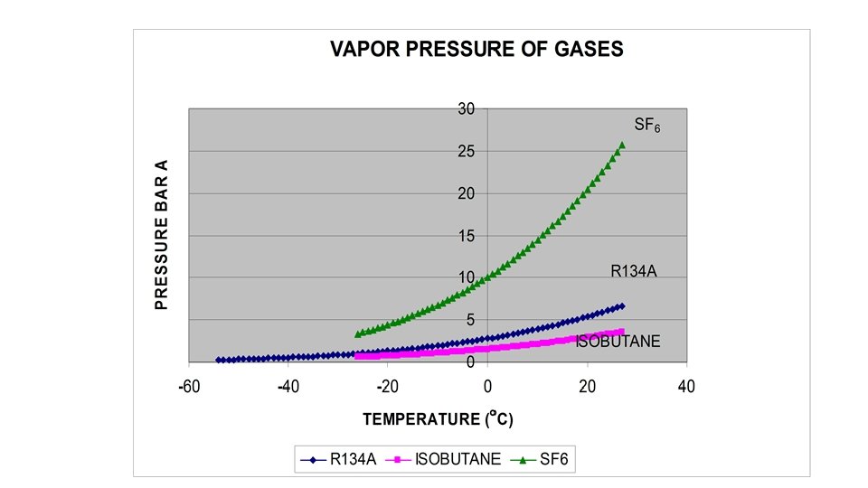
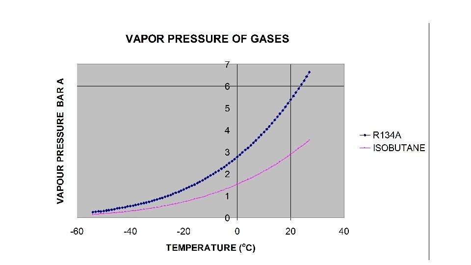
Process of liquefaction • • • Partial pressure of a gas is its contribution to the total pressure of gas mixture. Momentum of gas molecules changes with temperature. Mean Free Path changes with Pressure. Van Der Walls forces attach molecules together causing liquefaction. Increase of temperature increases kinetic energy of gas molecules and makes liquefaction more difficult. Increase of Pressure brings molecules closer and helps liquefaction. At combinations of temperature and pressure liquefaction takes place. Liquefaction does not take place above Critical Temperature at whatever applied pressure. The pressure required to cause liquefaction at critical temperature is critical pressure. Gas above critical temperature behaves as Ideal gas.
Properties of Components of Gas mixture at Exhaust of RPC S. N Gas/Vapour Density Kg/M 3 @ 0 C 1 Bar. A Boiling point C @ 1 Bar. A Relative presence in RPC gas mixture 1) R 134 a Freon 4. 25 -26. 3 95% 2) Isobutane 2. 51 -11. 7 4. 5% 3) Oxygen 1. 42 -183. 0 1000 ppm 4) Nitrogen 1. 25 -195. 8 4000 ppm 5) Water Vapour 0. 59 1000 ppm 6) Fluorine 1. 696 -188. 1 Less than 1000 ppm 7) Sulphur Dioxide 2. 63 -10. 0 Less than 1000 ppm 8) Sulphur Hexafluoride 6. 17 -64. 0 5000 ppm 9) Carbon Dioxide 1. 997 -78. 5 1000 ppm
Limitations of Open Loop system • Recovery is possible as long as only one gas component goes in liquid phase at one time • Heat Transfer rate plays important part in deciding condensation rate • Low concentration gases such as can not be recovered. • Cross contamination of gases in liquid phase is possible.
Problems with open loop system • Very small gas mixture have been tried to condense ( 6 SCCM), produces negligible liquid volumes. • Lab air has 40% RH. Leaked Humidity condenses at 0 C • 1) Moisture in Leaked air has dew point above 0 C • 2) moisture condenses over porous Palladium catalyst greatly reducing active surface area available for adsorption of Isobutane. • 3) Cross contamination of isobutene in liquid R 134 a increases to the point of non- separation
Advantage of Open loop gas recirculation system • It is easier to extract target gases by condensation than to remove impurities by adsorption • R 134 a is the target gas and is expensive • If R 134 a can be extracted to 99% , and Isobutane to 70% then the process becomes very efficient. • Cooling curves indicate that a mixture of 95% R 134 a is cooled at -5 C and below then 80% R 134 a will come out as liquid. But remaining 20% will be difficult to extract unless a process for further concentration is added
Effect of centrifugal force on gas mixture • At SINP Kolkata (India) and TIFR Mumbai (India) gas systems are operating with RGA • When analyzing RPC gas mixture with RGA measurement, it was noticed that for a certain transient period , Isobutane concentration was found to be lower than its actual value. • The difference was found to be dependent on the background pressure in RGA cell ( 10 E-4 to 10 E-7 m. Bar). At lower pressures measured isobutane concentration was closer to its actual value. • Turbo molecular momentum transfer pump was used. • It was concluded that this effect was due to density and viscosity difference between Isobutane and R 134 a
Using a batch type centrifuge to separate Heavy gas from Light gas •
Batch Type Centrifuge 30000 to 70000 RPM Rotating Aluminum Cylinder r= 5 cm r=0 r=rmax
High Speed Rotation Aluminium Hollow cylinder
Conditions for Effective Centrifugal concentration • Large value of ∆M , difference in molecular mass • All gases must show Ideal gas behavior even after concentration. • One or two target gases , all others to be decomposed and converted to safe compounds. • From economy and maintenance point of view , not more than three stages should be required. • Centrifuge must operate under Angular speed of 70000 RPM ( Speed of Turbo molecular Pump)
Profile of Gases after centrifugal separation • AA • At r = 0 : Isobutane , oxygen, small fraction of freon , Nitrogen , CO 2 • Water Vapour, Light Radicals • At r = rmax : Large quantity of Freon , Heavy Radicals • Gases are pumped out from r=0 and r=r max • Discharge at r= rmax can be treated to extract R 134 a by condensation • Discharge at r=0 can be collected and reacted chemically or made to pass through microbore capillary to further separate Isobutane • Second stage condensation will further extract R 134 a and make efficiency better.
70 mm dia turbo molecular pump with Centre Cap. Transient increase in concentration of R 134 a upto 2% was found (95% to 97%)
• Reference : 1) Separation od Carbon dioxide and Methane in continuous countercurrent gas centrifuges Ralph Van Wissen , Michael Golomok , J. J. H. Brouwers Chemical Engineering Science 60 (2005) 4397 -4407
Acknowledgements • Prof. Avijit Ganguli , BHU (MMV) , India for analysis • Mr. Piyush Verma , TIFR, Mumbai