Performance characteristics Static characteristics Dynamic characteristics Static chracteristics


Detector-transducer stage,")
=Am- A")


 Instrumental Error These")
 Environmental Errors Due to conditions external to the measuring device such as the")


 Static Correction")


- Slides: 30
Performance characteristics • Static characteristics • Dynamic characteristics
Static chracteristics • • • Instrument Measurement Accuracy Precision Sensitivity Resolution Error Expected value Uncertainty Threshold
Dynamic Characteristics • • • Dynamic Error Fidelity Speed Response time Measuring LAG
LOADING EFFECT • When an instrument of lower sensitivity is used with a heavier load the measurement it makes is erroneous, this effect is known as loading effect. Example - Consider a lower sensitivity (ohm per volt) voltmeter being used with a high resistance load.
• In measurement system, when on introducing an element, used for any purpose (May be for signal sensing, conditioning, transmission or detection), into the system, the original signal remains undisturbed i. e. , introduction of any element in a measurement system should not distort the original signal in any form. • However in practical conditions it has been found that when an element is introduced in a measurement system, in extracts some energy from the system and, therefore, original signal is distorted. Such distortion may take the form of attenuation, waveform distortion, phase shift and many a time all these undesirable features put together. Thus ideal measurement is not practical. The incapability of the system to faithfully measure, record or control the input signal (measure and) in undistorted form is known as the loading effect
• A measurement system consists of three distinct stages that are (i)Detector-transducer stage, (ii)Signal conditioning stage including original transmission stage (iii) Signal presentation stage Loading effect not only occur at first stage but also may occur in any of the two Subsequent stages. In measurement system, we deal both electrical and mechanical quantities and Elements and so the loading effect may occur on account of both electrical and Mechanical elements. The loading effects are due to impedances of various Elements connected in a system.
Error in measurement • Am- Measured value • A-True value δA (Absolute error)=Am- A Relative error, εr = δA/A= εo /A= Absolute error/True value When the absolute error εo= δA is negligible, when the difference between measured value Am and true value A is negligible then relative error may be expressed εr= δA/Am % of error= εr * 100= (εo /A ) *100
Example 1 The expected value of the voltage across a resistor is 50 V; however, measurement yields a value of 49 V. Calculate a) The absolute error b) The percent of error • Solution • Yn-Expected value, Xn-Measured value a) e = Yn – Xn = 50 V – 49 V = 1 V b)
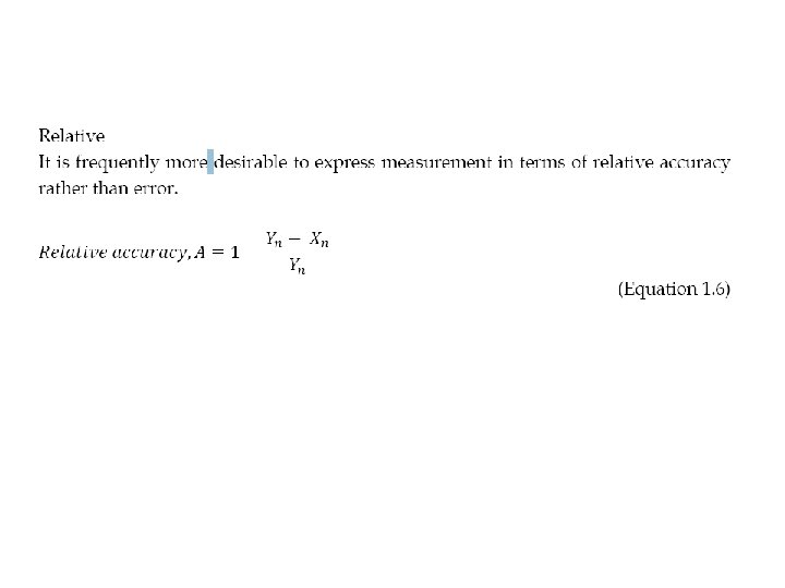
Accuracy Percent accuracy, a = 100% - percentage of error • = A X 100%
The expected value of the voltage across a resistor is 50 V; however, measurement yields a value of 49 V. Calculate a) The relative accuracy b) The percent of accuracy
TYPE OF ERROR Errors are generally categorized under the following three major types • Gross error • • • This class of errors is generally the fault of the person using the instruments such as incorrect reading of instruments, incorrect recording of experimental data or data incorrect use of instruments. As long as human beings are involved, some gross errors will definitely commit. Although complete eliminating of gross errors is probably impossible, one should try to avoid them. The following actions may be necessary to reduce the effects of gross errors. a) Great care should be taken in reading and recording the data. b) Two or more readings should be taken by different experimenters
Systematic error Systematical errors can be divided into four categories: a) Instrumental Error These errors arise due to main reasons: i. Due to inherit shortcoming in the instruments (may be caused by the construction, calibration or operation of mechanical structure in the instruments). ii. Due to misuse of the instruments. For example, these may be caused by failure to adjust zero of the instruments. iii. Due to loading effect of the instruments. These errors can be eliminated or at least reduced by using the following methods: a) The procedure of measurements must be carefully planned. b) Correction factors should be applied after detection of these errors. c) Re-calibration the instrument carefully. d) Use the instrument intelligently. b) Observational Errors i. Due to the types on instrument display, whether it is analog or digital. ii. Due to parallax (eye should be directly in line with the measurement point).
c) Environmental Errors Due to conditions external to the measuring device such as the area, surrounding the instrument. These conditions may be caused by the changes in pressure, humidity, dust, vibration or external magnetic or electrostatic fields. These errors can be eliminated or reduced by using corrective measure such as: i. Keep the condition as constant as possible. ii. Use instrument/equipment which is immune to these effects. iii. Employ technique which eliminates these disturbances. d) Simplification Errors Due to simplification of a formula: For example: A = B + C + D 2. If D is too small, then the formula is simplified to: A = B + C. There will be a different result between the first and the second equation. In high accuracy requirements, a formula should not be simplified to avoid these types of errors.
3. Random error • In some experiments, the results shows variation from one to another, even after all • systematical and gross errors have been accounted for. The cases of these errors are • not recognized, therefore the elimination or reduction of these errors are not possible. • When these types of errors are occurred, the best result can be determined by • statistical analysis.
Classification of instruments Absolute instruments Secondary instruments • They gives the magnitude of the quantity under measurement in terms of physical constants of the instrument. • So constructed that the quantity being measured can only be measured by observing the output indicated by the instruments. These instruments are calibrated by comparison with an absolute instrument.
Deflection type instrument Null type instruments • PMMC • DC potentiometer
Analog and Digital modes of Operation Analog mode Digital Mode • Signals that vary in continuous fashion and take on an infinite number of values in any given range are called analog signals. • Signals which vary in discrete steps and thus take up only finite different values in a given range are called digital signals.
Functions of instruments and measurement system • Indicating function • Recording function • Controlling function
Applications of measurement systems • Monitoring of processes and operations • Control of process and operations • Experimental Engineering analysis
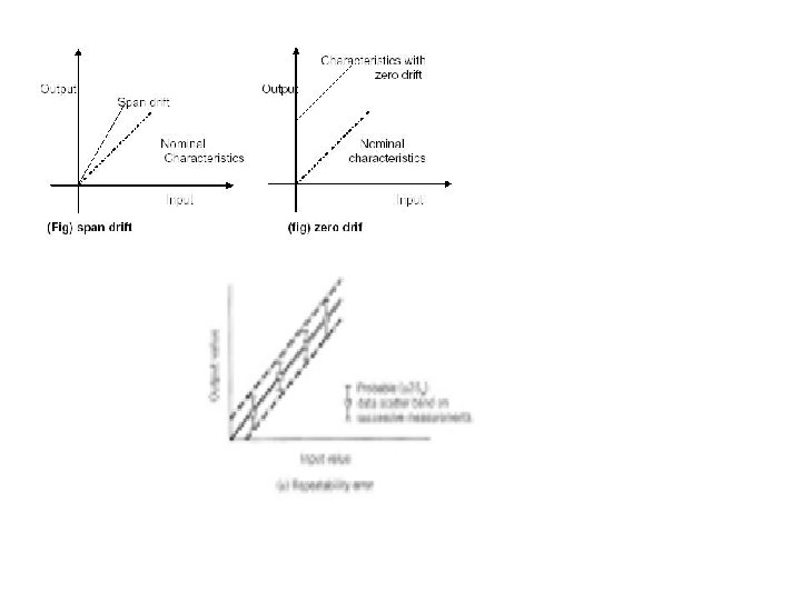
Errors in measurement • • True Value Static Error (measured value-true value) Static Correction (true value-measured value) Scale Range and Scale span Error calibration curve Reproducibility and drift Repeatability Noise
Noise • Extranous of current or voltage in an electrical or electronics circuit is called Noise. What is Signal to Noise Ratio? Types of Noises?
Signal to Noise Ratio • Unwanted signal superimposed upon the signal of interest and causes a deviation of output. S/N=Signal power/Noise Power = (Signal of interest expressed in volts)2/ (Unwanted noise expressed in volts)2
Sources of Noise • Generated Noise • Conducted Noise • Radiated Noise
Generated Noise • Possible sources of noise are-resistor, capacitors, transistors so called generated Noise. • This vibratory motion of atoms is transferred to the conduction electrons, thereby producing a noise component of current. Since this noise is temperature dependent, it increases with internal heating (I 2 R loss), this is called Johnson noise. • Vibrations produced by thermal effects within a resistor cover a wide frequency range, and therefore the noise Generated consists of a wide spectrum of Frequencies. This wideband noise is Sometimes called White noise. Shot noise
Conducted Noise • The power supply to the amplifier could be the source of noise since it may have spikes, ripple or random deviations that are conducted to the amplifier through power wiring. This type of noise is called Conducted Noise.
Radiated Noise • There may be electric or magnetic field disturbance in the environments around the amplifier because of which unwanted signals are radiated into the interior of the amplifier and this is called radiated noise.
Johnsan noise • Derivation