Performance and operation of the ATLAS Semi Conductor


![Hamburg/Dortmund Model • Based on Moll’s thesis [1], the leakage current coefficient a is Hamburg/Dortmund Model • Based on Moll’s thesis [1], the leakage current coefficient a is](https://slidetodoc.com/presentation_image/97b4eb6dc5eff3d7876732cb9cee2912/image-24.jpg)
- Slides: 24

Performance and operation of the ATLAS Semi Conductor Tracker (SCT) Paul Dervan The University of Liverpool, UK on behalf of the ATLAS SCT Collaboration RD 13 Florence, July 2013 1

Outline • • ATLAS and the SCT Silicon and modules Operation Radiation Damage RD 13 Florence, July 2013 2

ATLAS • Size: 25 m × 44 m • Weight: 7000 Tons • Sub detectors: • Tracking • Calorimeters • Muon RD 13 Florence, July 2013 3

The Semi Conductor Tracker (SCT) 1. 4 m 5. 6 m • 61 m 2 of silicon with 6. 3 million readout channels • 4088 silicon modules in 4 Barrels and 18 EC disks • C 3 F 8 Cooling (-7°C to +6°C silicon) RD 13 Florence, July 2013 4

SCT module layout Endcap side-A side-C disk 1 disk 8 9 4 5 disk 6 disk 7 disk 3 disk 2 disk Barrel B 6 B 5 B 4 B 3 outer inner middle short IP modules with Hamamatsu sensors modules with Ci. S sensors RD 13 Florence, July 2013 5

SCT Sensors • Single sided p-in-n • 285μm thick • 768+2 AC-coupled strips • • • Barrel: 8448 barrel sensors 8081 sensors with <111> 367 sensors with <100> 64. 0 × 63. 6 mm 2 80 μm strip pitch 100% Hamamatsu • • • Endcap: 6944 wedge sensors 56. 9 -90. 4μm strip pitch 4 different shapes 74. 9% Hamamatsu <111> 17. 1% CIS <111> 8. 0% CIS oxygen-enriched Barrel sensors (Hamamatsu) Endcap sensors (Ci. S) RD 13 Florence, July 2013 6

SCT Modules • 2 sensors connected by wire bonding to form 12 cm long strips • 4 sensors/module • Glued back to back with < 8μm accuracy between two planes • Stereo angle 40 mrad • Thermal pyrolitic graphite (TPG) heat spreaders for good thermal conduction and mechanical strength • Cu-Polyimide flexible circuits • 12 bi-CMOS binary readout chips (128 ch) with 1 f. C threshold • Power: 6 W (chips) and 2 W (sensors) • Radiation length 1. 17%X 0 (barrel) Thermistors for temperature meas. RD 13 Florence, July 2013 7

SCT operation and performance • Keeping a low percentage of defect chips/modules (as of Feb 2013) defect components Endcap SCT Fraction(%) components Total Barrel modules 4088 11 19* 30 0. 73 % chips 49056 38 11 49 0. 10 % strips 6279168 4111 8020 12131 0. 21 % * Due to one cooling loop failure • Mainly thanks to built-in redundancy. RD 13 Florence, July 2013 8

Track Efficiency • High efficiency for charge particles > 99. 5% at 8 Ge. V • Stop-less recovery of the ROD busy case • Periodical auto-configuration of modules RD 13 Florence, July 2013 9

SCT Cooling • C 3 F 8 evaporative system • Very stable operation • To be replace by thermo-siphon system during LS 1 Cooling pipes Number of active cooling loops RD 13 Florence, July 2013 10

Hybrid Temperature Barrel Red: link 0 (outer face) Blue: link 1 (inner face) • Very uniform in ϕ and z direction • Bumps in B 3 is due to one cooling loop set to a higher value • Sensor temperature = hybrid temp – 3. 7°C (FEA results) RD 13 Florence, July 2013 11

Noise (response curve) Oct. 2010 Dec. 2012 • Noise (response curve) is deduced from the width of threshold curves at 2 f. C charge injection in the gain calibration runs. • Middle Ci. S modules show ~10% increase from 2010 to 2012 RD 13 Florence, July 2013 12

Noise of each module (EC) Hamamatsu: red: C-side blue: A-side Ci. S: green: C-side pink: A-side • Middle Ci. S module (green, pink) show excess noise • Inner Ci. S modules (O 2 enriched) stay comparable with others RD 13 Florence, July 2013 13

Stability of Noise and Gain Luminosity middle (Ci. S) <100> inner (HMT/Ci. S) short middle (Ci. S) • ENC of <111> modules decreased in 2010 with chip # dependency • Middle Ci. S modules show increase of 10% in ENC in 2012 • All chip gain decreased in mid 20122 RD 13 Florence, July 2013 14

HV Current (Barrel Dec 2012) Raw HV current observed. Temperature corrected current at 0 o. C, assuming all are due to the bulk leakage current. Scaling formula of bulk leakage current: RD 13 Florence, July 2013 15

Evolution of Leakage Current and model Prediction SCT Barrel • The data are the average current at 0°C from module with HV > 140 V • The lines are prediction by Hamburg/Dortmund module using temperature sensor data • Results from FLUKA simulations are used to convert the delivered Lumi into 1 Me. V neutron-equivalent fluence at corresponding barrel layers RD 13 Florence, July 2013 16

Estimated radiation level by the end of 2012 1015 cm-2 1013 1014 1015 1016 Fn-eq [cm-2] 1 Me. V n-eq fluence received 12 13 13 12 2. 7 x 10 B 6: 2. 8 x 10 B 0: 136. 6 x 10 B 2: B 1: 1. 7 x 10 B 3: 5. 1 x 10 Integrated luminosity delivered = 5. 8 (7 SCT RD 13 Florence, July 2013 Pixel Te. V) + 23. 8 (8 Te. V) fb-1 + using the Fluka simulation 17

Raw HV (EC) Hamamatsu: red: C-side blue: A-side Ci. S: green: C-side pink: A-side • Modules of side-A systematically show higher current by ~20% (due to N 2 temperature) • Disks 8 and 9 show higher current (expected from FLUKS simulations) • Difficult to normalize to 0°C due to large uncertainty in sensors temperature (work in progress) RD 13 Florence, July 2013 18

Anomalous Ci. S Currents • In May 2012 we started getting unrecoverable ROD busy after a few hours of stable beam (high luminosity) • It was due to high current of EC middle Ci. S modules • The HV current varies during the beam time • Tentative solution: standy-by voltage kept at 5 V (normal 50 V) • Some sensors now operate at lower bias voltages, but this only marginally affecting efficiency Online display Example of HV current deterioration red : Bias Voltage , blue : HV Current RD 13 Florence, July 2013 19 19

Anomalous Ci. S Currents… • HV/Current profiles in early Nov 2012 with long stable beam runs • Typical 3 modules with HPK (left) and Ci. S (right) sensors • The last run is a day-long calibration run (no beam) • All Hamamatsu modules show stable current with/without beam • Ci. S modules simultaneously (but with different amount) exhibit similar current shapes only during beam time, in both sides A and C. However, the current shape differs run by run. Excess current disappears by turning HV down to 5 V during stand-by. RD 13 Florence, July 2013 20

Sensor Differences Points of differences Manufacturers Hamamatsu Ci. S Bias resistors (1. 25 MW) polysilicon implant meander Al strip/implant widths 22/16 mm 16/20 mm single ring, floating 11+5 p+ rings, potential by punch-through current Si. O 2 and Si 3 N 4 unpolished standard (middle) oxygen-enriched (inner) no a problem at low(<30%) RH Guard ring Front surface passivation Rear metal HV contact Bulk material Micro-discharge RD 13 Florence, July 2013 21

Summary • The Barrel layer B 3 received 5 x 10¹² 1 Me. V neq cm-2 fluence by the end of 2012. • The cooling system has been working very well sustaining the uniform and stable temperatures for all modules. • The noise (ENC) and gain have been rather stable except for noise of the middle modules with Ci. S sensors. • The HV current at 150 V steadily increased. Barrel layers show very flat distribution. The model predictions including annealing effects reproduce the leakage current within 1σ (~20%) with no parameter re-adjustments. • All modules with Ci. S sensors are showing simultaneously anomalous current. No such anomalies are seen in any of modules with Hamamatsu sensors. RD 13 Florence, July 2013 22

Backup RD 13 Florence, July 2013 23
![HamburgDortmund Model Based on Molls thesis 1 the leakage current coefficient a is Hamburg/Dortmund Model • Based on Moll’s thesis [1], the leakage current coefficient a is](https://slidetodoc.com/presentation_image/97b4eb6dc5eff3d7876732cb9cee2912/image-24.jpg)
Hamburg/Dortmund Model • Based on Moll’s thesis [1], the leakage current coefficient a is given by Krasel [2] is: Note : last two equations in [2] are corrected here. [1] M. Moll, DESY-THESIS-1999 -040 (Dec 1999) [2] Oraf Krasel, Dortmund Dissertation, July 2004 RD 13 Florence, July 2013 24
 Semiconductors
 Energy band diagram of pn junction diode
 Boundary conditions between conductor and free space
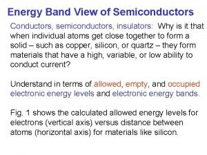
 Energy band in conductor semiconductor and insulator
 Boundary conditions between conductor and free space
 Difference between dielectric and conductor
 Insulators
 Insulator things
 Hát kết hợp bộ gõ cơ thể
 Slidetodoc
 Bổ thể
 Tỉ lệ cơ thể trẻ em
 Voi kéo gỗ như thế nào
 Chụp phim tư thế worms-breton
 Hát lên người ơi
 Các môn thể thao bắt đầu bằng tiếng bóng
 Thế nào là hệ số cao nhất
 Các châu lục và đại dương trên thế giới
 Công thức tính thế năng
 Trời xanh đây là của chúng ta thể thơ
 Mật thư anh em như thể tay chân
 Làm thế nào để 102-1=99
 độ dài liên kết
 Các châu lục và đại dương trên thế giới
 Thể thơ truyền thống

