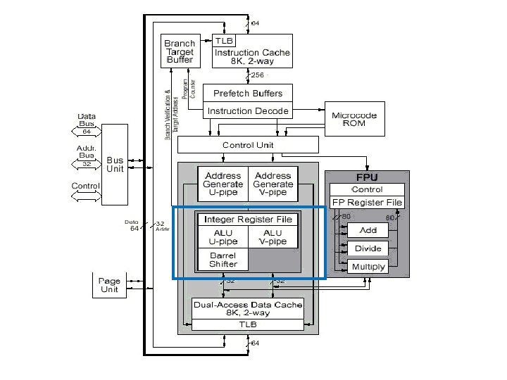
Pentium Architecture ArithmeticLogic Units ALUs There are two
 : – There are two parallel integer instruction")
")


 : –")

: – The instruction is executed in ALU – Data")
- Slides: 20
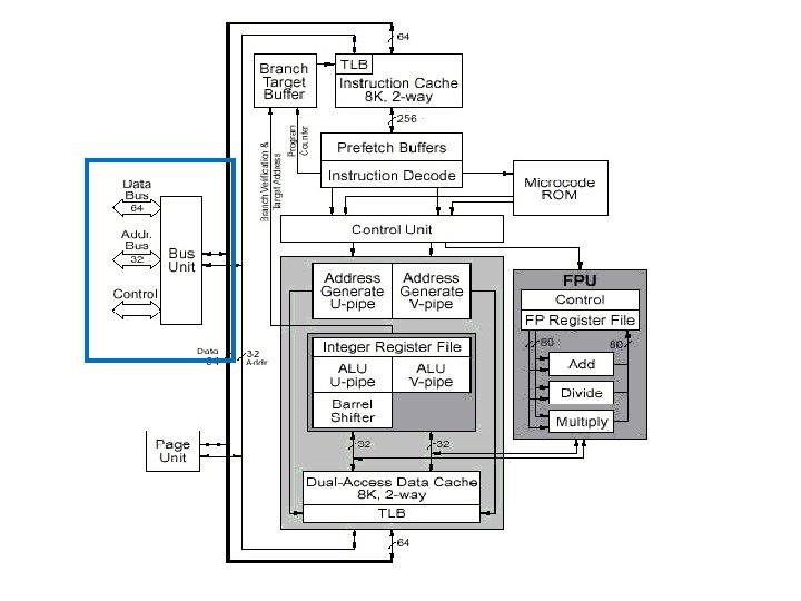
Pentium Architecture • Arithmetic/Logic Units (ALUs) : – There are two parallel integer instruction pipelines: u-pipeline and v-pipeline – The u-pipeline has a barrel shifter – The two ALUs perform the arithmetic and logical operations specified by their instructions in their respective pipeline
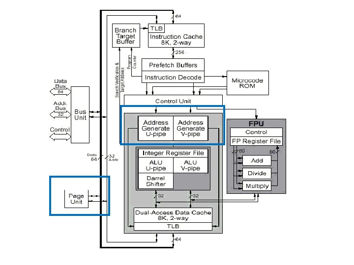
Pentium Architecture • Address Generators : – Two address generators (one for each pipeline) form the address specified by the instructions in their respective pipeline. – They are equivalent to segmentation unit. • Paging Unit : – If enabled, it translates linear address (from address generator) to physical address – It can handle two linear addresses at the same time to support both pipelines with one TLB per cache
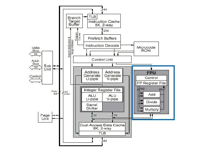
Pentium Architecture • Floating Point Unit: – It can accept upto two floating point operations per clock when one of the instruction is an exchange instruction – Three types of floating point operations can operate simultaneously within FPU: addition, division and multiplication.
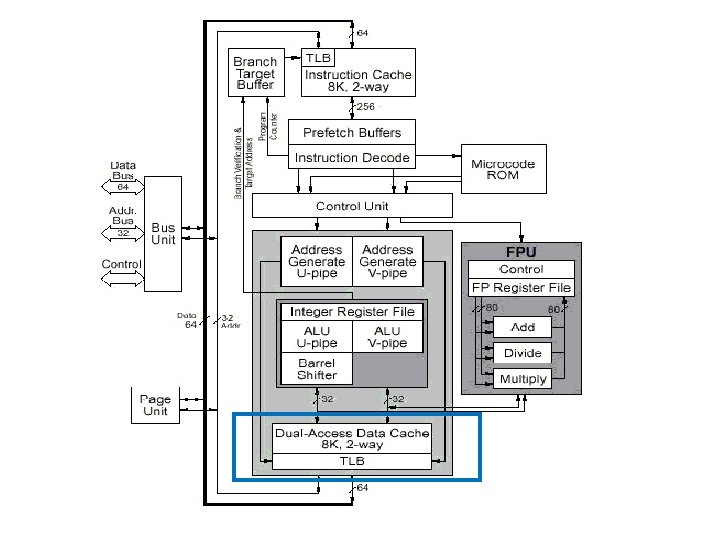
Pentium Architecture • Data Cache: – It is an 8 KB write-back two way set associative cache with line size of 32 bytes
Pentium Architecture • Bus Unit: • Address Drivers and Receivers: – Push address onto the processor’s local address bus (A 31: A 3 and BE 7: BE 0 ) • Data Bus Transceivers: – gate data into the processor ‘s local data bus • Bus Control Logic: – controls whether a standard or burst bus cycle is to be run
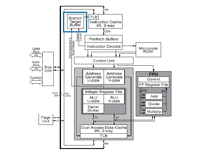
Pentium Architecture • Branch Target Buffer: supplies jump target prefetch addresses to the code cache
Superscalar Operation • The prefetcher sends an address to code cache and if present, a line of 32 bytes is send to one of the prefetch buffers • The prefetch buffer transfers instructions to decode unit • Initially it checks if the instructions can be paired.
Superscalar Operation • If paired, one goes to ‘u’ and other goes to ‘v’ pipeline as long as no dependencies exist between them. • Pair of instructions enter and exit each stage of pipeline in unison
Superscalar Operation • Pentium uses a five stage execution pipeline as shown:
Integer Pipeline UQ: Explain in brief integer instruction pipeline stages of Pentium
Integer Pipeline • The pipelines are called “u” and “v” pipes. • The u-pipe can execute any instruction, while the v-pipe can execute “simple” instructions as defined in the “Instruction Pairing Rules”. • When instructions are paired, the instruction issued to the v-pipe is always the next sequential instruction after the one issued to u-pipe.
Integer Pipeline • The integer pipeline stages are as follows: 1. Prefetch(PF) : – Instructions are prefetched from the on-chip instruction cache 2. Decode 1(D 1): – Two parallel decoders attempt to decode and issue the next two sequential instructions – It decodes the instruction to generate a control word
Integer Pipeline – A single control word causes direct execution of an instruction – Complex instructions require microcoded control sequencing 3. Decode 2(D 2): – Decodes the control word – Address of memory resident operands are calculated
Integer Pipeline 4. Execute (EX): – The instruction is executed in ALU – Data cache is accessed at this stage – For both ALU and data cache access requires more than one clock. 5. Writeback(WB): – The CPU stores the result and updates the flags