
PEF 3208 Aula do dia 662019 Prof Nakao

- Slides: 35
PEF 3208 Aula do dia 6/6/2019 Prof. Nakao baseado nos textos de TA Philpot Missouri University of Science and Technology
Historical development • Leonardo da Vinci (1452 – 1519) and Galileo Galilei (1564– 1642) investigated the behavior of bars under loads. • Robert Hooke (1615– 1703) was the first to show that a body is deformed if a force acts upon it. • Sir Isaac Newton (1642– 1727) developed the concepts of Newtonian mechanics. • Leonard Euler (1707– 1783) presented the mathematical theory of columns in 1744. • Thomas Young (1773– 1829) established a coefficient of elasticity called, Young’s modulus.
Historical development • Coulomb, Poisson, Navier, St. Venant, Cauchy, and many other scientists and engineers were responsible for advances in mechanics of materials during the nineteenth century. • Over the years, Stephan P. Timoshenko (1878– 1972) made many original contributions to the field of applied mechanics, and wrote many textbooks in this area.
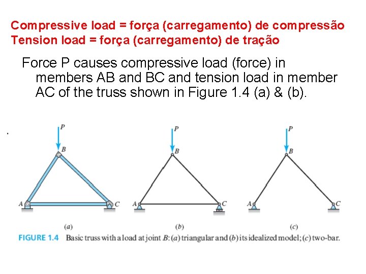
Compressive load = força (carregamento) de compressão Tension load = força (carregamento) de tração Force P causes compressive load (force) in members AB and BC and tension load in member AC of the truss shown in Figure 1. 4 (a) & (b).
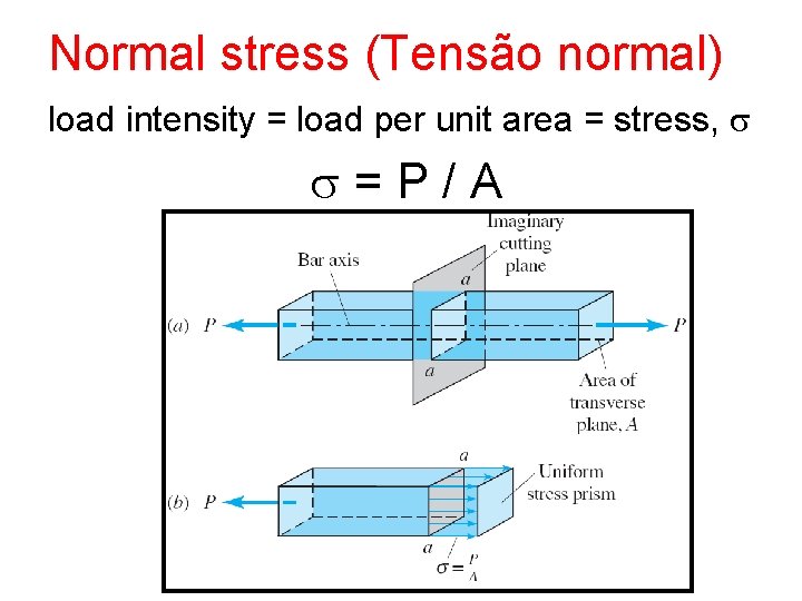
Normal stress (Tensão normal) load intensity = load per unit area = stress, s s = P / A
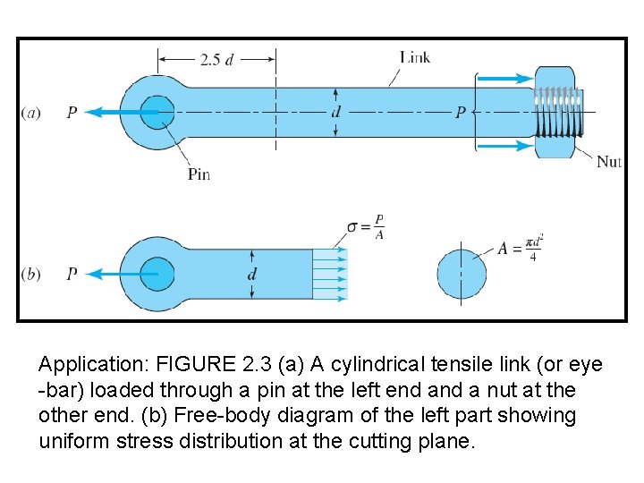
Application: FIGURE 2. 3 (a) A cylindrical tensile link (or eye -bar) loaded through a pin at the left end a nut at the other end. (b) Free-body diagram of the left part showing uniform stress distribution at the cutting plane.
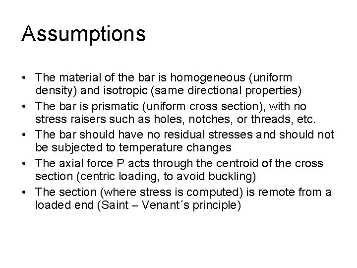
Assumptions • The material of the bar is homogeneous (uniform density) and isotropic (same directional properties) • The bar is prismatic (uniform cross section), with no stress raisers such as holes, notches, or threads, etc. • The bar should have no residual stresses and should not be subjected to temperature changes • The axial force P acts through the centroid of the cross section (centric loading, to avoid buckling) • The section (where stress is computed) is remote from a loaded end (Saint – Venant´s principle)
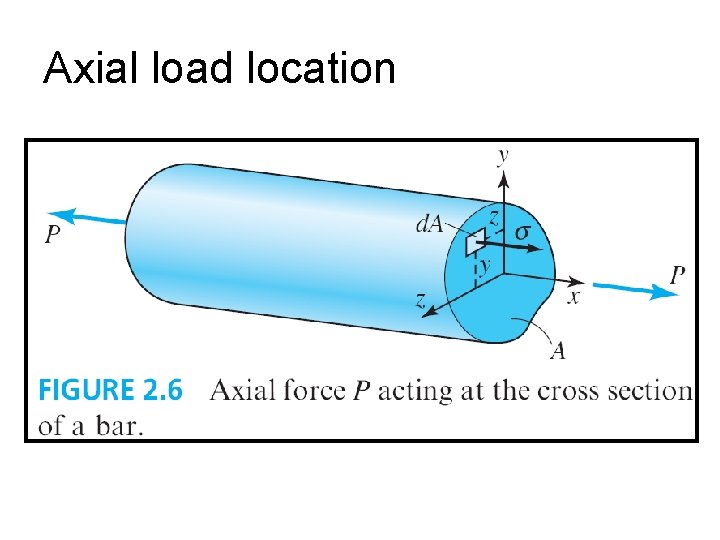
Axial load location
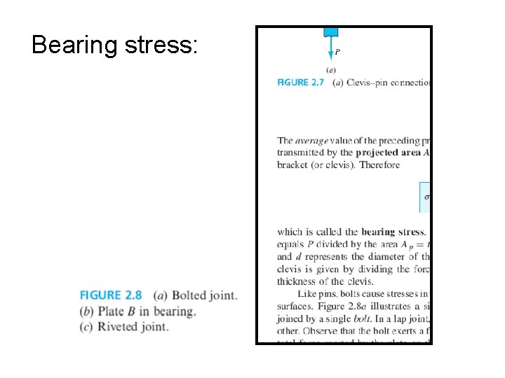
Bearing stress:
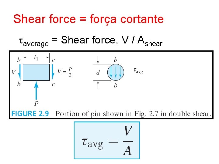
Shear force = força cortante taverage = Shear force, V / Ashear
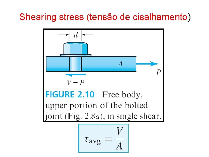
Shearing stress (tensão de cisalhamento)
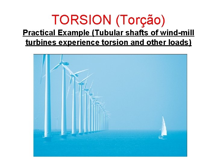
TORSION (Torção) Practical Example (Tubular shafts of wind-mill turbines experience torsion and other loads)
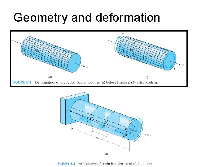
Geometry and deformation
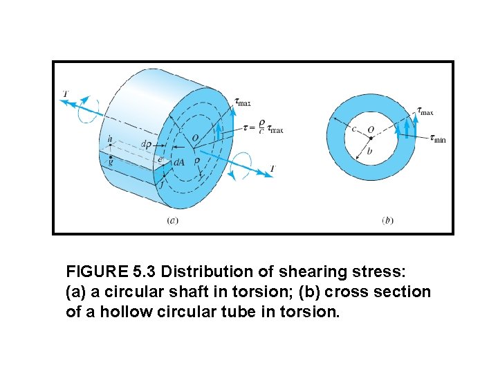
FIGURE 5. 3 Distribution of shearing stress: (a) a circular shaft in torsion; (b) cross section of a hollow circular tube in torsion.
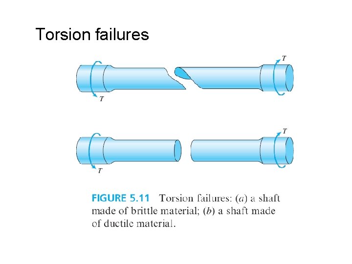
Torsion failures
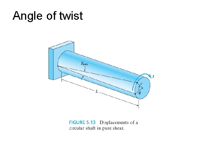
Angle of twist
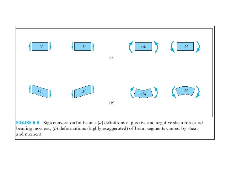
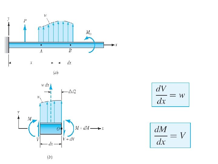
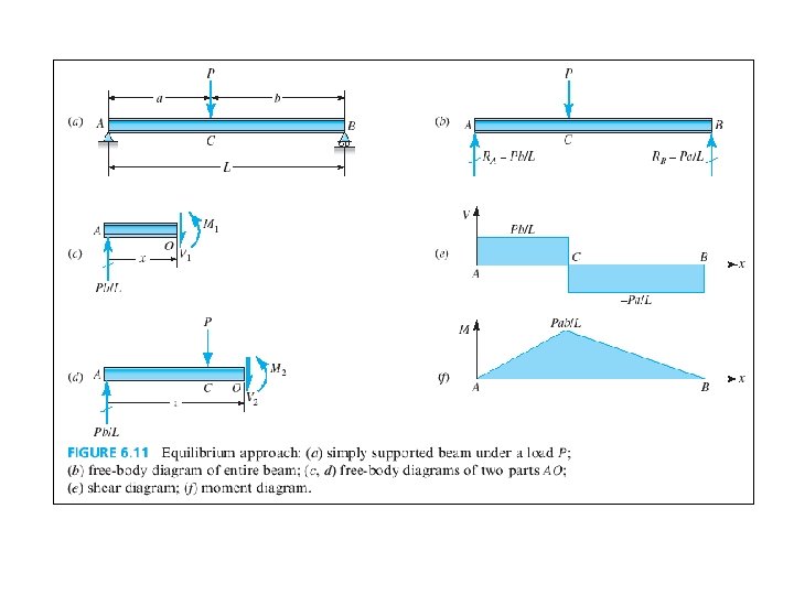
SHEAR AND MOMENT IN BEAMS Shear force = força cortante Bendind moment = momento fletor
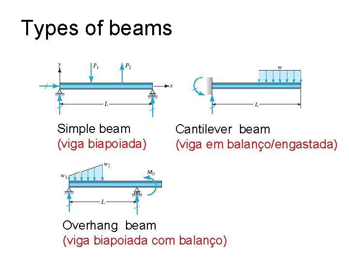
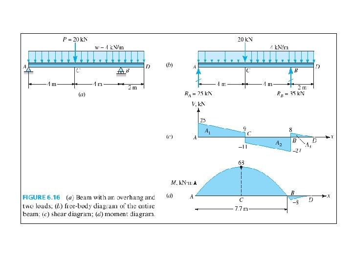
Types of beams Simple beam (viga biapoiada) Cantilever beam (viga em balanço/engastada) Overhang beam (viga biapoiada com balanço)
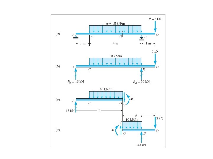
Calculation of beam reaction forces Equations of static equilibrium are used to determine the reaction forces of a loaded beam. Self weight (peso próprio) of the beam is usually neglected unless otherwise specified.
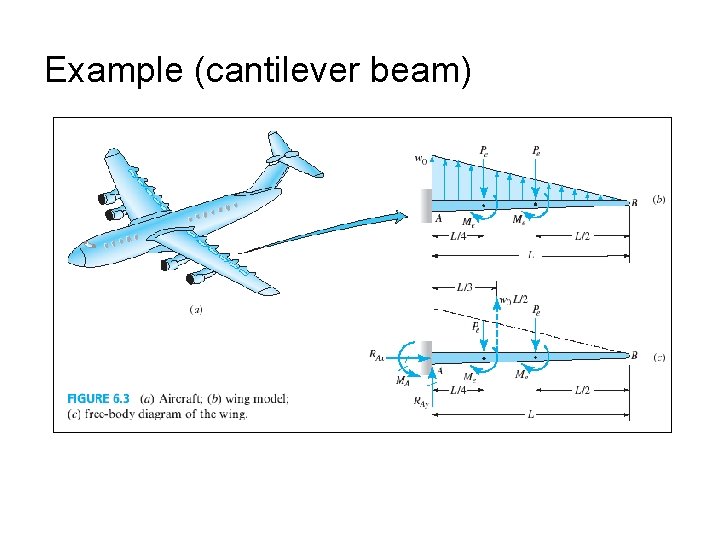
Example (cantilever beam)
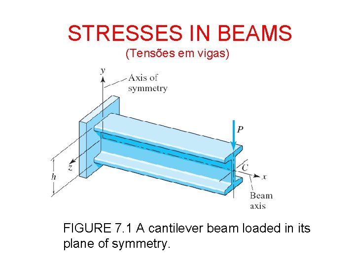
STRESSES IN BEAMS (Tensões em vigas) FIGURE 7. 1 A cantilever beam loaded in its plane of symmetry.
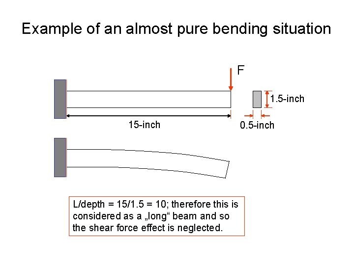
Example of an almost pure bending situation F 1. 5 -inch 15 -inch 0. 5 -inch L/depth = 15/1. 5 = 10; therefore this is considered as a „long“ beam and so the shear force effect is neglected.
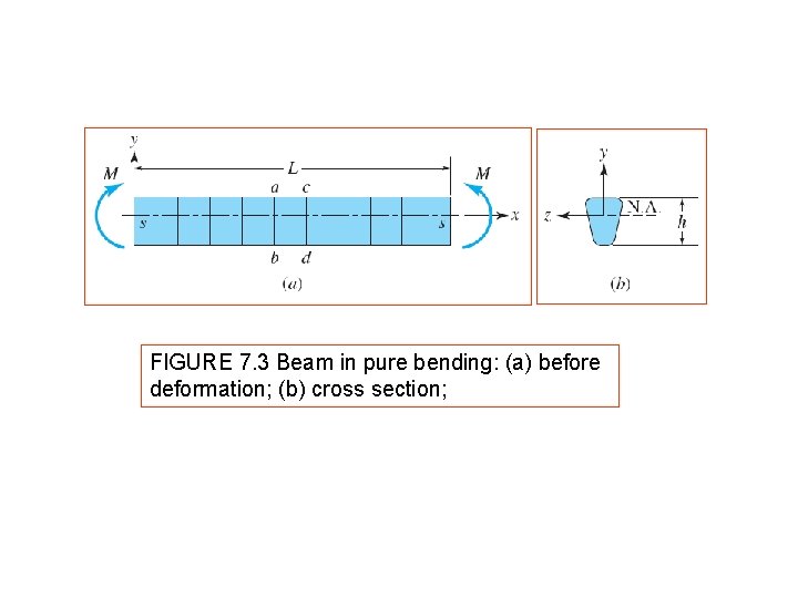
FIGURE 7. 3 Beam in pure bending: (a) before deformation; (b) cross section;
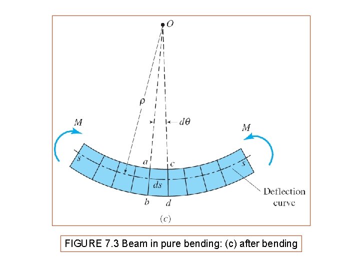
FIGURE 7. 3 Beam in pure bending: (c) after bending
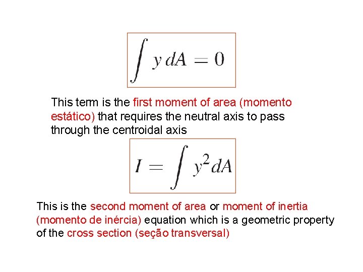
This term is the first moment of area (momento estático) that requires the neutral axis to pass through the centroidal axis This is the second moment of area or moment of inertia (momento de inércia) equation which is a geometric property of the cross section (seção transversal)
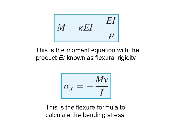
This is the moment equation with the product EI known as flexural rigidity This is the flexure formula to calculate the bending stress
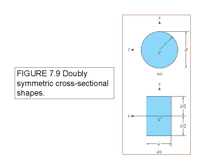
FIGURE 7. 9 Doubly symmetric cross-sectional shapes.
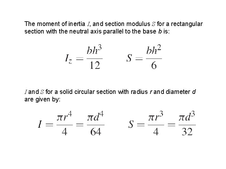
The moment of inertia I, and section modulus S for a rectangular section with the neutral axis parallel to the base b is: I and S for a solid circular section with radius r and diameter d are given by:
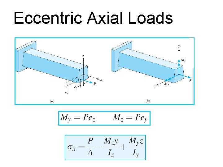
Eccentric Axial Loads