PEAK INVERSE VOLTAGE l Using the ideal diode


 The conducting diodes (D 1 and D 3")


 (2) (3) Make a sketch in your mind about")

 (2) There are two general categories of the clippers.")


- Slides: 27
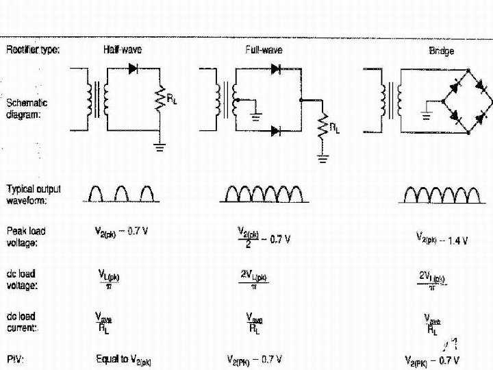
PEAK INVERSE VOLTAGE l Using the ideal diode model, the PIV of each diode in the bridge rectifier is equal to V 2. This is the same voltage that was applied to the diode in the full-wave center -tapped rectifier. Following fig helps us to illustrate this point. Fig in next slide , two things have been done :
PEAK INVERSE VOLTAGE
PEAK INVERSE VOLTAGE l l 1) The conducting diodes (D 1 and D 3 ) have been replaced by straight wires. Assuming that the diode are ideal they will have the same resistance as wire; therefore replacement is valid. 2) The positive side of the secondary has been labeled A and the negative side has been labeled B.
PEAK INVERSE VOLTAGE l Connecting the common A point along a straight line and doing the same with B points gives us the circuit shown in the fig b. With the equivalent circuit , you can see that two reverse biased diodes and the secondary of the transformer are all in parallel. Since parallel voltages are equal , the PIV across each diode is equal to V 2. The same situation will exist for D 1 and D 3 when they are reverse-biased.
FILTERS l Filters are used in power supplies to reduce the variations in the rectifier output signal. Since our goal is to produce a constant dc output voltage, it is necessary to remove as much of the rectifier output variations as possible.
FILTERS l The overall result of using a filter is illustrated
CLIPPERS l There are variety of diode networks called clippers that have the ability to clip off a portion of the input signal without distorting the remaining part of the alternating waveform. The half wave rectifier studied earlier is a simplest form of diode clipper.
CLIPPERS l Depending on the orientation of the diode, the positive or negative region of the input signal is “clipped” off.
IMPORTANT POINTS FOR CLIPPERS (1) (2) (3) Make a sketch in your mind about the response of the network. Determine the applied voltage (Transition Voltage) that causes change in the diode bias. Be continuously aware of the defined terminal and polarity of Vo.
IMPORTANT POINTS FOR CLIPPERS Sketch the input signal on the top and the output at the bottom to determine the output at instantaneous points of the input. (4)
TYPES OF CLIPPERS l (1) (2) There are two general categories of the clippers. Series Parallel
SERIES CLIPPERS l The series configuration is defined as one where the diode is in series with the load as half wave rectifier.
EXAMPLES
ADDITION OF A BATTERY IN THE SERIES CLIPPER CIRCUIT l In the fig. the direction of the diode suggests that the signal Vi must be positive to turn it on. The dc supply further requires that the voltage Vi be
ADDITION OF A BATTERY IN THE SERIES CLIPPER CIRCUIT greater than V volts to turn the diode on. The negative region of the input signal is pressuring the diode into off region.
ADDITION OF A BATTERY IN THE SERIES CLIPPER CIRCUIT l Now we determine the applied voltage that will cause a change in state for the diode. The ideal diode transition occur at the point on the characteristic where Vd= 0 and Id = 0
ADDITION OF A BATTERY IN THE SERIES CLIPPER CIRCUIT l In this case transition will occur at Vi = V
ADDITION OF A BATTERY IN THE SERIES CLIPPER CIRCUIT When the diode is short circuited as shown in the fig. The out put voltage V 0 can be calculated bu applying KVL Vi – V - V 0 = 0 V 0 = Vi – V
ADDITION OF A BATTERY IN THE SERIES CLIPPER CIRCUIT l In this case V 0 = Vm - V
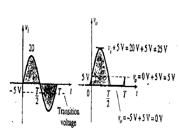
EXAMPLE l Determine the output waveform for the network shown
SOLUTION The equivalent circuit will be V 0 = Vi + 5 V Transition voltage =5 V l
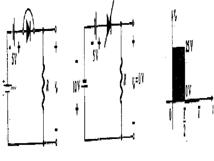
EXAMPLE l Determine the output for the square wave input shown in the fig. lec 39_m
SOLUTION l In positive half cycle. The diode is in the short circuit condition and by KVL V 0= 20 + 5 = 25 V
SOLUTION l For the negative half cycle Vi = -10 V the result in placing the diode in the reverse condition.