PDT 352 MOLD AND DIE DESIGN Chapter 4


 –")


 Conventional milling: work")


 According to the method of presenting the workpiece to")


 • Workpiece can be quickly mounted & removed •")

")
")


 1 hour 2 Questions")
- Slides: 111
PDT 352 MOLD AND DIE DESIGN Chapter 4 Jigs and fixtures design
What are Jigs and Fixtures? • Anything used to hold a work piece in a desired location – Locate parts for precision – Repeating process on a series of parts – Holding parts for machining, painting, assembly
What are Jigs and Fixtures? § Jig and Fixture are production work holding devices used to manufacture duplicate parts accurately. § They are special purpose tools used for large scale production by semi skilled operator. § They can also be used for small scale production when interchangeability is important by skilled machinist when the workpiece is difficult to hold without special equipment.
Definitions • Jig: A device that holds the work and locates the path of the tool. • Fixture: A device fixed to the worktable of a machine and locates the work in an exact position relative to the cutting tool. Superior Jig Flexible Fixturing Systems
Purpose of Jigs & Fixtures They are used in industry: § To reduce cost of production § To increase productivity § To assure accuracy of component § For mass production of component on its repeatability basis § For fully or partial automation of work § To increase the versatility of the machine tool § improve quality with greater machining accuracy
Jigs vs fixtures § Jigs and fixtures are so closely related that the terms are sometimes confused or used interchangeably. § The difference is in the way the tool is guided to the work piece. § Fixture locates, holds and supports the work securely so the required machining operation can be performed § Jig not only locates and supports the workpiece but also guides the cutting tool
Jigs vs fixtures • The main construction difference between a jig and a fixture is mass • Because of the increased tool forces , fixtures are built stronger and heavier than a jig would be for the same part • They are made basically the same way as far as locators and positioners are concerned
Jigs vs fixtures • The term jig should be used only for devices employed while drilling, reaming or tapping holes • It is not fastened to the machined on which it is used • So it may be moved around on the table of the drilling machine to bring each bushing under the drill • It is not fastened to the drill press table for small w. p, however holes above 0. 25 mm inch in diameter are to be drilled, it is usually necessary to fasten the jig to the table securely.
Jigs vs fixtures • Jigs make it possible to drill, ream and tap holes at much greater speeds and with greater accuracy • Skilled workers are not required • Responsibility for the accuracy of hole location is taken from the operator and given to the jig • Jigs physically limit and control the path of the cutting tool with the help of bushings
Jigs vs fixtures • For machining operations like milling, shaping, turning, broaching, etc. , the term fixture should be used • A fixture hold and locates the work during machining but does not contain special arrangements for guiding the cutting tools • A fixture is also fixed to the machine • The accuracy of machining depends upon the operator and construction of machine tool
Jigs
Two main types of jigs: • For machining purposes – Locates the component, holds it firmly in place, and guides the cutting tool. • For assembly purposes Northwestern Tools – Locates separate component parts and holds them rigidly in their correct positions while they are being connected.
TYPES OF DRILL JIGS • Open Jigs: Used for simple operations Work is done only on one side of the part • Closed or Box Jigs: Used for parts that must be machined on more than one side
Drill jig terms • Open jig (also called plate jig or drill template) – The simplest type of drill jig – Consists of a plate with holes to guide the drills, and may have locating pins that locate the workpiece on the jig
TEMPLATE JIGS § It is the form of jig consisting of a suitable material having holes for correct location § The plate serve as a template which is fixed on the component to be drilled. § Template jigs are normally used for accuracy rather than speed. § Used for locating hole pattern on large workpieces. § Usually not clamped (self-clamping). § It is the least expensive. § Simplest type of jigs. § They may or may not have bushings. When the bushings are not used, the whole jig plate is normally hardened.
• Drill bushings – Precision tools that guide cutting tools such as drill and reamers into precise locations in a workpiece. Accurate Bushing Co.
Operations Common to a Drill Jig
TEMPLATE JIGS
PLATE JIGS § It is the modified form of the template jig with jig bushes incorporated on the template. § Consist of a single bush plate with a provision for locating and clamping of w. p. § They have built-in clamps to hold the work. § They use a flat plate containing bushing as their main structural member. § All the details are attached and referenced to this plate. § May or may not have legs.
PLATE JIGS • Easy part loading and unloading, chip removal by providing clearance between plate and the workpiece. • Also called open jig. • Slip bushings for operations other than drilling. • Thin parts stacked for drilling several parts at one time. • These jigs are sometimes made with legs to raise the jig off the table for large work. This style is called a table jig. • The feet provide square resting surface to the jig. • The diameter of the jig feet should be bigger than the slot of machining table to prevent the feet from falling into the slots.
Plate jig examples
Plate jig examples
Table jig examples
SANDWICH JIGS § A form of plate jig with a back plate § The w. p is clamped like a sandwich b/w the base plate and the jig plate. § This type of jig is ideal for thin or soft parts that could bend or wrap in another style of jig. § Here, the use of bushings is determined by the number of parts to be made and diameter of the hole.
Sandwich jig example
PUMP or UNIVERSAL JIGS • They are similar version of sandwich jig. • Produced commercially as basic units and are adapted to specific jobs by tool makers. • The lever activated plate makes this tool very fast to load and unload. • Rigid, low weight, ample chip clearance and ease of operation. • Handle connected to a cam or rack to clamp workpiece. • It is also known as universal jig used for any given part by adding the necessary locators and bushes.
PUMP or UNIVERSAL JIGS • The guide pillars attached to the jig plate have rack gear teeth on one side. • Purpose of gear meshing by rotating the handle is to raise or lower the rack pillar with the jig plate. • Pump jigs are suitable for drilling only a single hole on a fixed spindle drilling machine. • One pump can be used for number of workpieces by providing detachable jig plate and base plate for different workpieces.
PUMP JIG
ANGLE-PLATE JIGS • Used to machine parts at right angles to their locators. • Pulleys and Gears use this type of jig.
MODIFIED ANGLE-PLATE JIG § which is used for machining angles other than 90 degrees. § Both of these examples have clearance problems with the cutting tool.
Modified angle-plate jig examples
Modified angle-plate jig examples
BOX JIGS • Surround the part totally. • Shape resembles a box. • In the figure, for loading, the cam rod is taken out of the jig and the w. p placed in position inside the jig. • The cam rod is then replaced and rotated to its locking position. • This holds the work-piece firmly so that the drilling operation can be performed. • Such jigs are generally used for components having irregular shapes or that cannot be held by common methods.
BOX JIGS • Number of holes can be drilled economically with box jig. • One side is open for loading and unloading the w. p and provided bushing arrangements. • The box jig can permits drilling of holes in three sides of the work-piece and saves times and increase production.
Box jig examples
CHANNEL JIGS • It’s a type of box jig. • The work-piece is mounted against the top and one side of the jig. • It is clamped from the third side. • Provides better stability and support for workpiece. • This type is limited to work-pieces of simple symmetrical shapes. • It mainly consist of the jig body, jig bush and screws and w. p is clamped inside the channel with the help of screw.
CHANNEL JIGS
LEAF JIGS • They are similar to box jigs, but main differences are size and part location. • Distinguished by their hinged cover, or leaf • Leaf carrying the bushing can be swung open to load and unload quickly • Suitable for complicated workpieces with irregular contours • Equipped with a handle for easy movement • It consist of drill bush, hinge pin, set screw leaf • Chips may accumulate inside and cause trouble
Leaf jigs examples
Leaf jigs examples
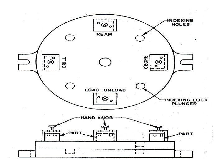
INDEXING JIGS § Many components require holes at stated angular positions. § Used to drill a series of holes in a circle on the face of a work-piece under a single bushing. § Brings the hole portion under the drill each time it is indexed. § To do this a reference plate and a plunger is used. § For this purpose multi head machine is used at regular intervals. § The operation can also be performed on single spindle machine.
Indexing jigs examples
V-BLOCK JIGS • Used to drilling radial holes in cylindrical or spherical workpiece. • It mainly consist of the V-block clamping plate. • The component is placed on the V-block and clamped rigidly by means of a clamping plate and bolt.
V-BLOCK JIGS • These jigs may also be called diameter jigs by some toolmakers.
VISE JIGS • Constructed by attaching special inserts to the jaws of a regular machine vise. • Generally used for low volume and short production runs. • It is generally used for drilling the shafts and consists of a pair of specially designed jaws, setting stops and support.
MULTISTATION JIGS § Commonly used on multi-spindle machines. § Facilitates more than one workpieces at a time. § For example one part being drilled, another can be reamed and third counter-bored. § The final station is used for unloading the finished part and loading fresh part. § It is the complex and specialized type of the jig that cannot be further classified and skilled worker is required to operate.
GENERAL CONSIDERATIONS IN THE DESIGN OF DRILL JIGS Rigidity: • Jig must be strong enough to withstand all forces applied to it. • It must also resist deflections that may be the result of excessive tightening of clamps that hold the w. p in place. • The work must also be supported so that it does not bend under drilling pressure. • Cast iron is generally used because it absorb shocks and compressive forces.
GENERAL CONSIDERATIONS IN THE DESIGN OF DRILL JIGS § The type of machine in which operation is performed needs careful considerations. § The layout of the jig must provide adequate hand clearance for easily loading and unloading and process for loading and unloading must be quick. § Errors arise in components due to wear, dirt, chips burns and wear resistance surfaces should be small and easily replaceable. § Bushes are provided on a jig for guiding drills, reamers and borings, for the desired positioning.
GENERAL CONSIDERATIONS IN THE DESIGN OF DRILL JIGS § To increase tool life and keep the components cool, a coolant is provided in cutting edge in sufficient quantity. § Design considerations require easy ejection of the component from jig (particularly for heavy ones) to save the operation time and increase the productivity, pneumatic devices are very suitable for easy and quick ejection.
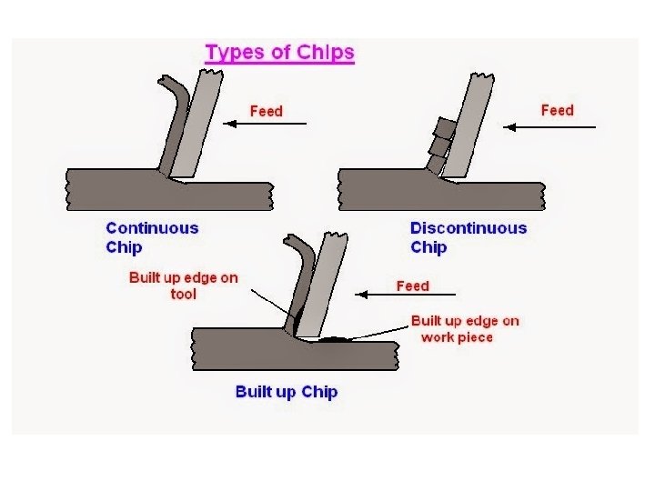
GENERAL CONSIDERATIONS IN THE DESIGN OF DRILL JIGS Chip Control: • Types of chips: segmental and continuous. • The segmental chip is preferred. • Space between the work and bottom of drill bushings to allow chips to pass b/w the work and busing plate (1 - 11/2 times dia. of drill). • Three ways of chip removal: coolant, manually with brush or hook, compressed air
Chip Control:
GENERAL CONSIDERATIONS IN THE DESIGN OF DRILL JIGS Jig feet and legs: • A drill jig should stand on four feet (Or legs). rather than a flat surface. • Jig feet may be built into the jig body or purchased as standard parts. • They are usually placed on the extremities of the jig. • Feet should be ground so that they are all in one plane after they are mounted on the jig base. • When jig is bolted to machine table, usually provides with four feet instead of a flat bottom, squaring provides easily chip removal and sustainability.
Types of Standard Jig Feet:
GENERAL CONSIDERATIONS IN THE DESIGN OF DRILL JIGS Miscellaneous considerations: • Sharp corners should be eliminated. • Provisions should be made for the coolant to get to the drill. • Holes or passages for escape of the coolant. • Gripping surfaces should be knurled. • The jig should be large enough to hold it against the torque of the drilling machine. • It must be easy to handle.
METHODS OF CONSTRUCTION • Generally jigs are constructed by holding the components together mechanically. • This is referred to as built-up construction. • Adv. : All parts can be completely machined before assembly and worn parts can be easily replaced. • Minor adjustments can be made during assembly. • Jigs of this type are held together by socket-head cap screws and dowels. • Screw serve to hold the components together while the dowels serve to hold the parts in alignment.
METHODS OF CONSTRUCTION • Welded construction is also used in building a drill jig. • Drill jigs are sometimes constructed by a combination of welding and mechanical assembly. • The main body may be of welded construction with the smaller components attached by screws and dowels. • The main body of a drill jig may also be cast.
Materials for Jigs and fixtures Following points for selection: § Easily available. § Ability to withstand the stress expected in service. § Ability to retain its shape and size. § Corrosion resistance. Ø Cast iron is generally used as materials for jig and fixture, light materials like brass, bronze, steels, plastic can also be used. Ø The choice of the proper material can also be selected when the operating conditions are known.
Fixtures
FIXTURES • Used to hold workpiece during machining. • Fixture is always fixed to the m/c table. • Classified by the type of machine on which they are used.
VISE FIXTURES
MILLING MACHINE VISES
VISE FIXTURES • Sometimes standard m/c vises are adapted with special jaws. • Special jaws are designed for workpieces with irregular contours. • Used with various types of m/c tools.
SPECIAL VISE JAWS
MILLING FIXTURES • Used to hold the w. piece in correct relation to the cutter. • Attached to m/c table with T-slots. PARTS OF MILLING FIXTURE: (1) Base (2) Clamps (3) Rest Blocks (4) Locating Points (5) Gaging Surfaces
BASE: • Consists of base plate with flat & accurate under surface. • Various components are mounted on it. • It mates with the surface of milling m/c table. • Used as reference plane. • Has slots to clamp fixture to the table. • It has a keyway running lengthwise in the base for two keys used to align the fixture on the milling machine table. • The keys are pressed into the keyway at both ends of the fixture and held there by socket-head cap screws.
BASE: • The fixture is attached to the millingmachine table and held in alignment by two keys attached to the fixture base. • These keys fit very closely into the T slot of the mill table. • The fixture is held firmly to the table by T bolts or hold-down clamps.
Underside of Mill-fixture Base
Data required before starting the design of a milling fixture • • • The type of milling machine Dimensions of T slots The center-to-center distance of T slots The dimensions of the milling machine table The length of table travel in all three feed movements v The center-to-center distance of T slots varies from machine to machine v If the fixture is to be used on more than one machine, it may be well to hold the fixture with strap clamps
Strap Clamp Holding Fixture to Machine Table
Effect of Cutting Forces on Workpiece at Beginning of Cut • Cutting forces exerted by a milling cutter change as the cutter leaves or enters the work and throw an extra load on clamps. • Clamps must not loosen by vibration caused by interrupted cutting of mill cutter. • Interrupted cutting occurs at the beginning and end of the cut.
Effect of Cutting Forces on Workpiece at Beginning of Cut (a) Conventional milling: work is lifted up at beginning of cut. (b) Climb milling: work is forced down at one end but lifted up at the other.
Accuracy of Contact Between Bearing Surface and Workpiece • A feeler gage of predetermined thickness is inserted between the bearing surface and the workpiece resting upon it • Bearing surfaces are usually in the form of pins, pads and plates
Use of Setting Gages to Locate Mill Fixture in Correct Relationship to Cutter
TYPES OF MILLING FIXTURES • Milling Fixtures can be classified in a variety of ways: (1) According to the way the workpiece is clamped, such as hand-clamping fixtures, power-clamping fixtures, toggle fixtures etc. (2) According to the way the workpiece is located, such as center fixtures, V-block fixtures etc.
TYPES OF MILLING FIXTURES (3) According to the method of presenting the workpiece to the cutter, as rotary fixtures where the workpiece is rotated under the cutter. Indexing fixtures where the workpiece is indexed into the next position during the machining cycle. (4) According to the milling operation performed on work, such as face-milling fixtures, slabmilling fixtures, slotting fixtures, string-milling fixtures etc.
MILLING FIXTURES STRING or LINE MILLING FIXTURES: • A number of components strung behind each other in a line • The fixture moves relative to the cutters
MILLING FIXTURES HYDRAULIC CLAMPING FIXTURE:
MILLING FIXTURES SPRING TYPE FIXTURE:
MILLING FIXTURES CLAMP TYPE FIXTURE:
MILLING FIXTURES • • • VACUUM FIXTURE: It’s a suction holding device Used where holding without distortion is vital Uses a vacuum pump Part acted upon by atm. Pressure It exerts a downward force on all sides exposed to vacuum
VACUUM FIXTURE
BROACHING FIXTURES • A broach is a series of progressively taller chisel points mounted on a single piece of steel • Use of a broach is to cut splines or a square keyway on objects such as gears, driveshafts, pulleys etc.
INTERNAL BROACHING FIXTURES
INTERNAL BROACHING FIXTURES
EXTERNAL BROACHING FIXTURES
GRINDING FIXTURES (Magnetic chucking devices) • Workpiece can be quickly mounted & removed • Distortion caused by mechanical clamping eliminated • Mild steel plates separated by nonferrous ones • Magnetic flux passes from magnetic chuck through steel plates and workpiece
GRINDING FIXTURES
GRINDING FIXTURES (use of magnetic chuck parallels)
GRINDING FIXTURES (use of magnetic-chuck V block)
GRINDING FIXTURES
LATHE FIXTURES Three-jaw Universal Chucks: • Three-jaw chucks used for circular and hexagonal work • Three-jaw chucks are usually self-centering • Three jaws move simultaneously when adjusted • This simultaneous movement is caused by a scroll plate into which all three jaws fit • They are usually provided with two set of jaws, one for outside chucking and the other for inside chucking
THREE-JAW UNIVERSAL CHUCK
LATHE FIXTURES Four-jaw Independent Chucks: • 4 -jaw chucks are usually non-self-centering • Each jaw can be moved independently • Ideal for gripping round, square, hexagonal and irregularly shaped workpieces • The jaws can be reversed to hold work by inside diameter • Multi-jaw chucks (6 or 8 jaws) for special purpose and high standards of accuracy
FOUR-JAW AND SIX-JAW CHUCKS
LATHE FIXTURES • • Magnetic Chuck: It has the advantage of holding iron or steel parts The parts that are too thin or that may be damaged if held in a conventional chuck Suitable only for light operations A magnetic chuck consists of an accurately centered permanent magnet face
MAGNETIC CHUCKS
LATHE FIXTURES • • Faceplates: Circular metal plate fixed to the end of spindle Used to hold work that is too large or of such a shape that it cannot be held in a chuck or between centers It has slots or threaded holes W. piece is clamped using T-nuts in the slots or threaded holes
FACEPLATE AND T-NUTS
FACEPLATES
FACEPLATES
LATHE FIXTURES Collet Chucks: • that forms a collar around the object to be held and exerts a strong clamping force on the object when it is tightened. • A external collet is a sleeve with a (normally) cylindrical inner surface and a conical outer surface • Used for very small parts
LATHE FIXTURES Collet Chucks:
LATHE FIXTURES Mandrels: • Mandrels are internal locators used for machining of the outside diameter of the workpiece concentric with finished bores. • Mandrels are shafts specially made to hold work to be machined concentrically around a previously bored or drilled hole • There are two general types, plain and expanding • Plain mandrels have a 0. 006 -in. taper foot • There must be a mandrel for each hole size
LATHE FIXTURES Plain Mandrels:
LATHE FIXTURES Sleeve-type Expanding Mandrels: • It is used for high degree of concentricity. • It provides the adjustment of locating diameter to suite the variation in the bore size of the workpiece.
LATHE FIXTURES Mandrel for Threaded Parts: • Used for holding previously threaded workpiece or w. p with internal threads
END
Assignment • Form a group of 4 members. • Find any video related to either jigs or fixtures application. • Prepare a brief written report (2 -3 pages) about the video. (Download front page from portal) • Present the video and brief report next week 23 Mac 2016 (week 6).
TEST 1 • • • 30 Mac 2016 (week 7) 1 hour 2 Questions (15 Marks each) Jigs and fixtures, types, applications Locating principles GD & T, tolerances, hole and shaft.