PDT 1103 METROLOGY CHAPTER 4 Measuring Instruments MEASURING


 • You must consider three factors when using a steel")


 • It is mainly used to measure the outside diameter of")


- Slides: 60
PDT 110/3 METROLOGY CHAPTER 4 Measuring Instruments
MEASURING INSTRUMENT Direct measurement Indirect measurement Linear measurement Precision Non-precision Type of measurement instrument Angular measurement Precision Non-precision
Linear measurement • Direct measurement – Rule – Vernier caliper, height gage, depth gage – Micrometer • Indirect measurement – Outer Caliper – Inner caliper – Divider
Linear measurement • Precision instrument – Micrometer – Vernier caliper, height gage, depth gage • Non-precision instrument – Rule – Divider – Calipers
Angular Measurement • Precision instrument – – – Universal bevel protractor Dividing head Spirit level Sine bar Angle gage block Auto collimator • Non-precision instrument – Protractor – Adjustable bevel – T-square Dividing head
Graduated Scales and Scaled instruments • Rule is also called as graduated scales. • The layout and inspection instruments (scaled instruments) can be divided into three groups: 1 st: rules with mechanical refinements to make them more useful, such as the combination square. 2 nd: related devices that are used with rules but are not rules themselves, like caliper. 3 rd: vernier instruments like vernier height gage which are the highly precise refinements of steel rule.
Direct measurement • Rules – Rules or graduated scales, are most commonly used in layout and inspection, the two opposite ends of the production process. – The simplest and most commonly used instrument is a steel rule, bar or tape with fractional or decimal graduation. – Rules can be rigid or flexible.
Steel Rule • Steel rules are all narrow steel strips with one set or more of graduated marks. • These marks are referred to as a scale. • The number of subdivisions of unit of length on a rule is called discrimination. • When you measure with a rule, you use the interchange method of measurement because you observe both ends of the part feature at the same time. • Measuring with a graduated rule is commonly called direct measurement.
Discrimination
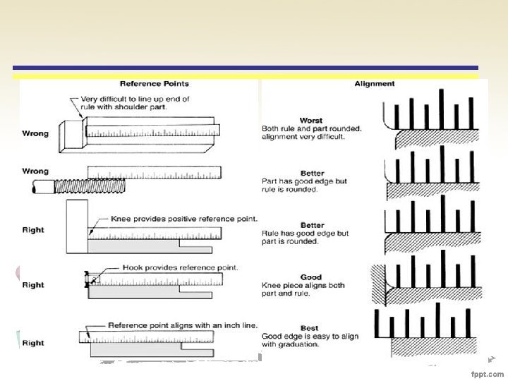
Steel rule (reference point) • You must consider three factors when using a steel rule: 1. Which style of rule do the best job. 2. Which measurement divisions (scale) should be used. 3. Which method of holding both rule and part allows us to obtain the most precise measurement. • These factors help us to the best relationship among the reference point on the part and the graduations of the rule.
The role of error of steel rule • Measurement errors with steel rules come from: i. Inherent instrument error or tool ii. Observational error of eye iii. Manipulative error of hand iv. Bias
i. Inherent instrument • Can be eliminated by choosing a quality steel rule. • Quality rules are engine engraved; a machine called ruling engine cuts each graduation. • Low cost rules are stamped or printed, whereas engine engraved are sharp.
ii. Observational error • Parallax is important form of observational error, in which an object appears to shift when observer changes his of her position. • To combat parallax; always place the scale edge of the rule as close as possible The observer B would correctly measure x as 16 division, While A would measure 15 and C would measure 17.
iii. Manipulative error • Many common manipulative errors are caused by ‘cramping ‘- the use of excessive force. • When you squeeze rule or other instrument tightly, you may forcing it against the part. • For reliable measurement, always use a light touch.
Manipulative Error
iv. The problem of bias • Bias means that we unconsciously influence each measurement we make. - Assume that the dimension need to be 14 cm (5 ½ in). - Because that graduation is easier to read than 13. 5 cm (5 31/64 in) or 14. 5 (5 33/64 in) cm, you might biased to read 14 instead of the accurate measurement.
MICROMETER INSTRUMENTS • • • Commonly used for measuring the thickness and inside or outside dimensions of part. All micrometers are based on the relation of a screw’s circular movement to its axial movement. Types of micrometer 1. 2. 3. 4. Outside Micrometer Inside micrometer Depth micrometer Others –e. g : i. wire micrometer ii. Screw thread micrometer
Outside micrometer
Outside micrometer (cont’) • It is mainly used to measure the outside diameter of a job or length of a small part. • It can measure dimension to an accuracy of 0. 001 mm. • The outside micrometers are available in the measuring ranges from 0 -25 mm, 25 -50 mm, 75100 mm and so on. • The largest measuring range available is 575600 mm.
Micrometer parts • Frame: The C-shaped body that holds the anvil and barrel in constant relation to each other. • Anvil: The shiny part that the spindle moves toward, and that the thing to be measured rests against. • Barrel/sleeve: Also called the stock. The stationary round part with the linear scale on it. Sometimes vernier markings. • Lock-ring/lock nut/thimble lock/Clamp ring: The knurled part (or lever) that one can tighten to hold the spindle stationary, such as when momentarily holding a measurement. • Screw (not seen): The heart of the micrometer. It is inside the barrel. • Spindle: The shiny cylindrical part that the thimble causes to move toward the anvil. • Thimble: The part that one's thumb turns. Graduated markings. • Ratchet stop: Device on end of handle that limits applied pressure by slipping at a calibrated torque.
Proper way to use micrometer
Inside micrometer
Inside micrometer • The inside micrometer is used for measuring large internal diameters (over 50 mm) to an accuracy of 0. 01 mm. • It work on the same principle as that outside micrometer. • Spindle/ extension rod of different length are provided in order to obtain a wide measuring range.
Depth micrometer • The depth gauge micrometer is a precision measuring instrument, used by engineers to measure depth of holes, slots and recessed areas to accuracy of 0. 01 mm. • They come in sets with different length depth rods of different ranges measurement. • The micrometer head acts as reference surface and is held firmly and perpendicular to the center line of the hole. • The ratchet is turned clockwise until the spindle face touches the bottom of the blind hole. • The scales are read in exactly the same way as the scales of a normal micrometer. • In using this instrument, it should be first ensured that the edge of the hole is free from burrs.
Depth micrometer
Wire micrometer • To measure diameter of wire
Screw thread micrometer • It is designed to measure the pitch diameter of screw thread to an accuracy of 0. 01 mm.
Screw thread micrometer • In order to measure the pitch diameter, the pointed end of the spindle and the sides of the veeenvil should contact the surfaces of the thread. • The reading on the micrometer is read in the similar way as in outside micrometer.
Reading a Micrometer
Advantages and disadvantages of micrometer
VERNIER INSTRUMENT • Vernier instrument are used most tool-rooms, die-making and laboratory work but rarely for modern production inspection. • Vernier instrument today includes: 1. Vernier caliper 2. Height gages, 3. Depth gages, 4. Gear tooth instrument
1. VERNIER CALIPER • It is a precision instrument which is used for measuring external as well as internal diameters to an accuracy of 0. 02 mm. • Vernier calipers are slide calipers with a vernier scale attached. • The principle of vernier is that when two scales or divisions slightly different in size are used, the differences between them can be utilised to determine the accuracy of measurement.
Parts of a vernier caliper 1. Outside jaws: used to measure external lengths 2. Inside jaws: used to measure internal lengths 3. Depth probe: used to measure depths 4. Main scale (cm) 5. Main scale (inch) 6. Vernier (cm) 7. Vernier (inch) 8. Retainer: used to block movable part to allow the easy transferring a measurement
Alignment consideration
2. VERNIER HEIGHT GAGE • It is mainly used for measuring heights of parts to an accuracy of 0. 02 mm. • The height gage is essentially a vernier caliper with an entire surface plate as its fixed jaw. • The surface plate is not part of height gage, but the height make efficient use of the surface plate, because the gage sits right on the plate. • In order to measure the height, the work is placed between the surface plate and the measuring face.
Vernier height gage
Height gage attachment 1. Scriber (the most important use of the scriber is for layout rather than measurement) See figure 4. 10. 2. Depth gage attachment (we can convert the instrument to a depth gage with very large range, which allow us to measure relative height differences in inaccessible.
Scriber Figure 4. 10
Depth gage attachment The depth gage attachment gets into otherwise inaccessible places
The problem with height gage • Instability – wobble (tall, thin column sways freely- can destroy the reliability of measurement • Magnification of setup errors – dirt, surface plate error, burr on height gage base • Magnification of instrument error – wear and abuse can disturb the squareness of the column to the base of the moveable jaw to the column.
Height gage error
Vernier gear tooth caliper • Used for measuring the thickness of a gear tooth at the pitch circle of a gear. • Consist of vernier caliper perpendicular to each other. • The horizontal caliper measures the tooth thickness is similar to an outside caliper. • Whereas the vertical caliper is adjusted for measuring the distance from the top of tooth to the pitch circle of the gear.
Vernier gear tooth caliper
How to read vernier instrument? 1. Read the number of the whole divisions on the main scale that appear to the left of zero (0) on the vernier. 2. Read the largest numbered graduation on the main scale that lies to the right of the index (0) on the vernier scale. 3. Read the largest whole mirror division to the right index. 4. Find the vernier graduation that most exactly coincide with any graduation on the main scale. * Note: before using the instrument, it should be checked for zero reading. The zero line on the vernier scale should coincide with the zero on the main scale
Reading a vernier in inches
INDIRECT MEASUREMENT • Indirect-reading instruments are typically calipers or dividers without any graduated scales. • They are used to transfer the measured size to a directreading instrument such as a rule. • After adjusting the legs to contact the part at the desired location, the instrument is held against a graduated rule, and the dimension is read. • Accuracy of indirect measurement is limited.
Indirect measurement Inside caliper Outside caliper Divider
Indirect measurement • Outside caliper – Have their legs bent inward and hinged at the top. – For checking or measuring outside dimensions or plate thickness. – A steel rule must be used with the caliper when direct reading is required. • Inside caliper – Have their leg bent outwards. – For checking or measuring the internal dimensions of recesses, hole diameters and parallel surfaces of inside dimension. – A steel rule requires to obtain specific reading. • Divider – This tool used for transferring dimensions, marking out curves and circles and for doing general layout work.
ANGULAR MEASUREMENT • Bevel protractor – A bevel protractor is a direct-reading instrument similar to a common protractor, except that it has a movable element Will be discussed details in chapter 7
• Sine bar – Measuring with sine bar involves placing the part on a inclined bar or plate and adjusting the angle by placing gage blocks on a surface plate. – After the part is placed on the sine bar, a dial indicator is used to scan top surface of the part. Will be discussed details in chapter 7
OTHER MEASUREMENT INSTRUMENTS • • Feeler gage Screw pitch gage Dial indicator Profile projector
Feeler gage • A feeler gage is a simple tool used to measure gap-widths. • Feeler gauges are mostly used in engineering to measure the clearance between two parts. • They consist of a number of small lengths of steel of different thicknesses with measurements marked on each piece. • They are flexible enough that, even if they are all on the same hinge, several can be stacked together to gauge intermediate values. • ** clearance – a space between two parts
Screw pitch gage • The use of screw pitch gage provides quick and accurate method of checking the thread pitch of a fastener. • The leaves of this measuring tool are marked with the various pitch. • To check the pitch, simply match the teeth of the gage with the threads of the fastener. • Then read the pitch from the leaf. Ref : J. Erjavec, Automatic Transmission, Thomson Delmar Learning, 2004
Dial indicator • Dial indicators are simple mechanical devices. • Convert linear displacements of a pointer to the amount of rotation of an indicator on a circular dial. • The indicator is set to zero at a certain reference surface, and the instrument or the surface to be measured is brought into contact with pointer. • The movement of the indicator is read directly on the circular dial.
Profile projector • Profile projector is also commonly called as optical projector or optical comparator. • It is an instrument which projects the large shadow of the profile of the workpiece on a glass screen. • From this projection of the workpiece, measurement can be made directly or indirectly. • The profile projector has a table that can be moved laterally and from front to back. • The workpiece is placed on the table and moved into position so that its enlarged shadow comes on the screen. Ref: Serving Ohio, Kentucky & Indiana, Manufacturing technology, New Age Publishe, 2005
Profile projector • Profile projector consist of: i. Light source ii. A lens system (to direct the light past the workpiece) iii. A staging table iv. Projection optics (including both lens and table) v. Screen (where the workpiece image is projected)
Profile projector
References • Dotson C. L. , Fundamentals of Dimensional Metrology, Thomson Delmar Learning, 2006 • www. wikipedia. com • www. technologystudent. com • Webster. J, Outdoor Power Equipment, Thomson Delmar Learning, 2000 • J. Erjavec, Automatic Transmission, Thomson Delmar Learning, 2004 • Serving Ohio, Kentucky & Indiana, Manufacturing technology, New Age Publisher, 2005 • R. S Khurmi, J. K. Gupta, A textbook of workshop technology, S, Chand & Company LTD, 2001 • S. Kalpakjian & S. R. Schmid, Manufacturing Engineering and Technology, Prentice Hall, 2001
Any Question? ? Thanks