Pavement Structural Analysis 3 rd Stage Lecture 6


")


- Slides: 12
Pavement Structural Analysis 3 rd Stage Lecture 6 Lecture. Rana Amir Yousif Highway and Transportation Engineering Al-Mustansiriyah University 2018 -2019
References: � Nicholas J. Garber and Lester A. Hoel. ”Traffic and Highway Engineering”, Fourth Edition. � Yoder; E. J. and M. W. Witczak, “Principles of Pavement Design”, A Wiley- Interscience Publication, John Wiley & Sons Inc. , U. S. A. , 1975. � Yaug H. Huang, “Pavement Analysis and Design”, Prentic Hall Inc. , U. S. A. , 1993. � “AASHTO Guide for Design of Pavement Structures 1993”, AASHTO, American Association of State Highway and Transportation Officials, U. S. A. , 1993. � Oglesby Clarkson H. , “Highway Engineering”, John Wiley & Sons Inc. , U. S. A. , 1975.
Stresses in Layered Systems In actual case, flexible pavements are layered systems with better materials on top and cannot be represented by a homogeneous mass. Various multilayer theories for estimating stresses and deflections have been proposed. However, basic theories that utilize assumptions close to actual conditions in a flexible pavement are those proposed by Burmister first developed solutions for a twolayer system and then extended them to a three-layer system with the following basic assumptions: 1. Each layer is homogeneous, isotropic, and linearly elastic with an elastic modulus E and a Poisson ratio, ν. 2. The material is weightless and infinite in the lateral direction, but of finite depth, h, whereas the underlying layer is infinite in both the horizontal and vertical directions. 3. A uniform pressure q is applied on the surface over a circular area of radius a. 4. The layers are in continuous contact and continuity conditions are satisfied at the layer interfaces, as indicated by the same vertical stress, shear stress, vertical displacement, and radial displacement.
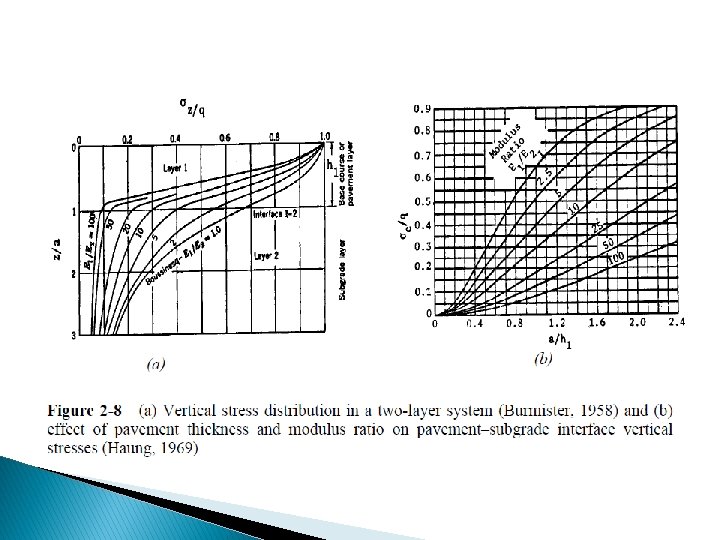
2. 1. Two-Layer Systems The exact case of a two-layer system is the full-depth asphalt pavement construction in which a thick layer of hot-mix asphalt is placed directly on the subgrade. If a pavement is composed of three layers (e. g. , surface course, base course, and subgrade) the stresses and strains in the surface layer can be computed by combining the base course and the subgrade into a single layer. Similarly, the stresses and strains in the subgrade can be computed by combining the surface course and base course. Vertical stress: The stresses in a two-layer system depends on the modulus ratio E 1/E 2, and the thickness-radius ratio h 1/a. Figure 2 -8 a shows the effect of pavement layer on the distribution of vertical stresses under the centre of a circular loaded area when the thickness h 1 of layer 1 is equal to the radius of contact area, or h 1/a = 1 and a Poisson ratio of 0. 5 for all layers. Figure 2 -8 b also shows the effect of pavement thickness and modulus ratio on the vertical stress, σc, at the pavement-subgrade interface.
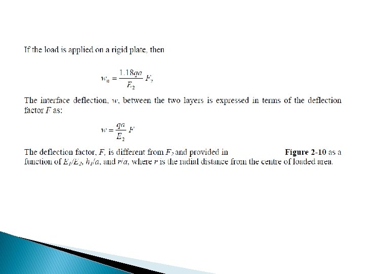
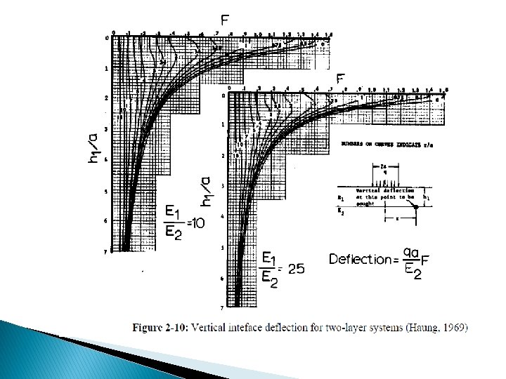
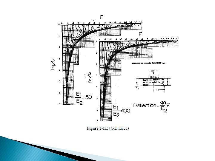
Deflection: Surface and interface deflections have been used as criteria of pavement design. The surface deflection, w 0, under a uniformly circular loaded area is given in terms of the deflection factor F 2 as: The deflection factor, F 2, can be obtained from Figure 2 -9 for the corresponding E 1/E 2 and h 1/a.
Figure 2 -9: Vertical surface deflection for two-layer system (Burmister, 1943)
Critical tensile strain: The tensile strains at the bottom of the asphalt layer have been used as a design criterion to prevent fatigue cracking. The critical tensile strain, e, at the bottom of the first layer for a two-layer system can be determined by
Where, Fe is the strain factor that can be obtained in Figure 2 -12 as a function of E 1/E 2, and h 1/a. The critical tensile strain under dual wheels or dualtandem wheels is obtained from the same equation, but the strain factor needs to be corrected.