PAVEMENT EVALUATION Pavement evaluation Functional evaluation Structural evaluation


 at a rate and accuracy")


 is")


![• Bitumen content = [(A-B)/B]× 100 % Repeat the test thrice and average](https://slidetodoc.com/presentation_image/139688bdec41606ab281bc532bb5cc6c/image-27.jpg "• Bitumen content = [(A-B)/B]× 100 % Repeat the test thrice and average")


 is a testing device used")


 mounted radially from the center of the load")
 into")


 describes tensile elasticity, or the tendency of")


 is a falling weight deflectometer")

- Slides: 45
PAVEMENT EVALUATION
Pavement evaluation Functional evaluation Structural evaluation Present serviceability index Pavement roughness Skid resistance Destructive testing Flexible pavements Non destructive testing Rigid pavements Coring /Bitumen extraction Crushing srength, flexural strength Static creep deflection method Steady state deflections Wave propagations Impulsive loading
• Pavement evaluations are conducted to determine functional and structural conditions of a highway section either for purposes of routine monitoring or planned corrective action.
• Functional condition is primarily concerned with the ride quality or surface texture of a highway section. • Structural condition is concerned with the structural capacity of the pavement as measured by deflection, layer thickness, and material properties.
Need of evaluation • At the network level, routine evaluations can be used to develop performance models and prioritize maintenance or rehabilitation efforts and funding. • At the project level, evaluations are more focused on establishing the root causes of existing distress in order to determine the best rehabilitation strategies.
Functional evaluation • Visual inspection /Present serviceability Rating • Roughness • Skid resistance
Present serviceability rating • Visual condition surveys cover aspects of both functional and structural pavement condition, but generally serve as a qualitative indicator of overall condition
Roughness • Profilometer is a measuring instrument used to measure a surface's profile, in order to quantify its roughness. • Roughness is a component of surface texture. • The profile of a road consists of road slopes, called grades, connected by parabolic vertical curves. • The road profile is the cross-sectional shape of the road surface in relation to the road corridor traversing the surrounding
profilometers
Cont. . , • The data collected by a profilometer is used to calculate the International Roughness Index (IRI) which is expressed in units of inches/mile or mm/m. • IRI values range from 0 (equivalent to driving on a plate of glass) upwards to several hundred in/mi (a very rough road). • The IRI value is used for road management to monitor road safety and quality issues.
Cont. . , • The IRI was defined as a mathematical property of a two-dimensional road profile (a longitudinal slice of the road showing elevation as it varies with longitudinal distance along a travelled track on the road). As such, it can be calculated from profiles obtained with any valid measurement method, ranging from static rod and level surveying equipment to high-speed inertial profiling systems.
• Some profilers take digital photos or videos while profiling the road. Most profilers also record the position, using GPS technology. • Some profilometer systems include a ground penetrating radar, used to record asphalt layer thickness.
Dipstick profilometer • Dipstick, “measures profiles (relative elevation differences) at a rate and accuracy greater than traditional rod and level surveys. ”
Skid resistance • Skid resistance is the force developed when a tire that is prevented from rotating slides along the pavement surface • Skid resistance depends on a pavement surface’s microtexture and macrotexture
• Microtexture refers to the small-scale texture of the pavement aggregate component (which controls contact between the tire rubber and the pavement surface) while • macrotexture refers to the large-scale texture of the pavement as a whole due to the aggregate particle arrangement (which controls the escape of water from under the tire and hence the loss of skid resistance with increased speed). . • For example, a road which has gravel spread on top followed by an asphalt seal coat will have a high macrotexture, and a road built with concrete slabs will have low macrotexture. For this reason, concrete is often grooved or roughed up immediately after it is laid on the road bed to increase the friction between the tire and road.
Variation of skid resistance • Skid resistance changes over time. Typically it increases in the first two years following construction as the roadway is worn away by traffic and rough aggregate surfaces become exposed, then decreases over the remaining pavement life as aggregates become more polished. • Skid resistance is also typically higher in the fall and winter and lower in the spring and summer.
Importance of skid resistance • Skid resistance is generally quantified using some form of friction measurement such as a friction factor or skid number. • In general, the friction resistance of most dry pavements is relatively high; wet pavements are the problem. The number of accidents on wet pavements are twice as high as dry pavements (but other factors such as visibility are involved in addition to skid resistance).
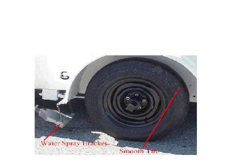
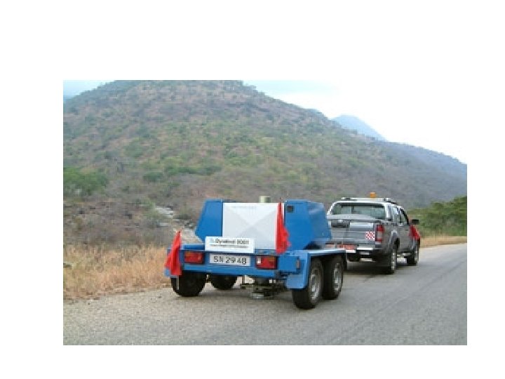
Lock wheel tester • The most commonly used method for skid resistance testing uses some form of a lock wheel tester. Basically, this method uses a locked wheel skidding along the tested surface to measure friction resistance. A typical lock-wheel skid measurement system must have the following: • A test vehicle with one or more test wheels incorporated into it or as part of a towed trailer. • A standard tire for use on the test wheel. The standardized skid-test tire, a tubeless, bias-ply G 78 x 15 tire with seven circumferential grooves, is defined by AASHTO M 261 or ASTM E 501. A newer tire, one with no grooves, appears to be gaining acceptance as well. By defining the standard test tire, the tire type and design are eliminated as variables in the measurement of pavement skid resistance. • A means to transport water (usually 750 to 1900 liters (200 to 500 gallons)) and the necessary apparatus to deliver it in front of the test wheel at test speed •
• A transducer associated with the test wheel that senses the force developed between the skidding test wheel and the pavement • Electronic signal conditioning equipment to receive the transducer output signal and modify it as required • Suitable analog and/or digital readout equipment to record either the magnitude of the developed force or the calculated value of the resulting Skid Number (SN)
Operation of the equipment • To take a measurement, the vehicle (or trailer) is brought to the desired testing speed (typically 64 km/hr (40 mph)) and water is sprayed ahead of the test tire to create a wetted pavement surface. The test tire braking system is then actuated to lock the test tire. Instrumentation measures the friction force acting between the test tire and the pavement and reports the result as a Skid Number (SN).
Structural evaluation of pavements • Destructive testing 1. Flexible pavements Bitumen extraction test • Rigid pavements 1. Flexural and crushing strength test • Non destructive testing
Destructive testing • Destructive testing provides more detailed data about the pavement not possible to obtain through non-destructive testing. Such detailed data include: • laboratory mechanical, physical, and chemical properties (obtained through coring and trenching), and • visual inspection of pavement layers through coring and trenching.
Destructive testing • Bitumen extraction test: This test is done to determine the bitumen content as per ASTM 2172. The apparatus needed to determine bitumen content are – i) Centrifuge extractor ii) Miscellaneous – bowl, filter paper, balance and commercial benzene. A sample of 500 g is taken.
Bitumen extraction • If the mixture is not soft enough to separate with a trowel, place 1000 g of it in a large pan and warm upto 100 o. C to separate the particles of the mixture uniformly. • ii) Place the sample (Weight ‘A’) in the centrifuge extractor. Cover the sample with benzene, put the filter paper on it with the cover plate tightly fitted on the bowl. • iii) Start the centrifuge extractor, revolving slowly and gradually increase the speed until the solvent ceases to flow from the outlet. • iv) Allow the centrifuge extractor to stop. Add 200 ml benzene and repeat the procedure. • v) Repeat the procedure at least thrice, so that the extract is clear and not darker than the light straw colour and record the volume of total extract in the graduated vessel. • vi) Remove the filter paper from the bowl and dry in the oven at 110 + 5 o. C. After 24 hours, take the weight of the extracted sample (Weight ‘B’).
• Bitumen content = [(A-B)/B]× 100 % Repeat the test thrice and average the results.
Non destructive testing • Non-destructive testing is the collective term for evaluations conducted on an existing pavement structure that do not require subsequent maintenance work to return the pavement to its pre-testing state. • This is generally desirable to minimize disruption to traffic, and is essential as a screening tool to determine locations where selective material sampling should be conducted to evaluate other material properties in the laboratory. • As such, its focus is to assess in situ properties that can be used to evaluate the need for further “destructive” testing (i. e. , coring, boring, trenching), location of that destructive testing, and the current structural capacity of the highway as related to layer stiffness
NDT Modulii of pavement layer Load transfer efficiency 1. 2. 3. 4. Static creep deflection method Steady state deflection method Wave propagation method Impulse loading method
Structural evaluation of pavements • Static creep deflection method: • Benkleman beam : • is used to measure deflections of flexible pavements. The light weight instrument is supplied in two parts for assembling on site with easy hand tools. • In use one end of the beam rests at a point under investigation while the beam is pivoted at the centre. The free end carries a dial gauge to record the deflections. • The other end is kept on a stable platform. • with a dial gauge 0. 01 x 25 mm. • This is a light weight dismantleable instrument and easy to carry
Falling weight deflectometer • A falling weight deflectometer (FWD) is a testing device used by civil engineers to evaluate the physical properties of pavement. FWD data is primarily used to estimate pavement structural capacity for • 1) overlay design and • 2) to determine if a pavement is being overloaded.
Impulse load • • An impulsive load Short loading time Weight falling on set of springs With proper choice of drop weight , spring constant, falling weight, impulsive load stimulating a real traffic load can be obtained.
deflection • deflection is the degree to which a structural element is displaced under a load. It may refer to an angle or a distance. • The deflection distance of a member under a load is directly related to the slope of the deflected shape of the member under that load and can be calculated by integrating the function that mathematically describes the slope of the member under that load
geophones • sensors (geophones; forcebalance seismometers) mounted radially from the center of the load plate measure the deformation of the pavement in response to the load. Some typical offsets are 0 mm, 200 mm, 300 mm, 450 mm, 600 mm, 900 mm, 1200 mm 1500 mm. The deflections measured at these sensors are termed D 0, D 200, D 300 etc.
Cont. . • A geophone is a device that converts ground movement (displacement) into voltage, which may be recorded at a recording station. The deviation of this measured voltage from the base line is called the seismic response and is analyzed for structure of the earth.
geophone
Elastic modulus • An elastic modulus, or modulus of elasticity, is a number that measures an object or substance's resistance to being deformed elastically (i. e. , non-permanently) when a force is applied to it. The elastic modulus of an object is defined as the slope of its stress– strain curve in the elastic deformation region: A stiffer material will have a higher elastic modulus.
Types of modulus • Young's modulus (E) describes tensile elasticity, or the tendency of an object to deform along an axis when opposing forces are applied along that axis; it is defined as the ratio of tensile stress to tensile strain. It is often referred to simply as the elastic modulus. • The shear modulus of rigidity (G or ) describes an object's tendency to shear (the deformation of shape at constant volume) when acted upon by opposing forces; it is defined as shear stress over shear strain. The shear modulus is part of the derivation of viscosity. • The bulk modulus (K) describes volumetric elasticity, or the tendency of an object to deform in all directions when uniformly loaded in all directions; it is defined as volumetric stress over volumetric strain, and is the inverse of compressibility. The bulk modulus is an extension of Young's modulus to three dimensions • Dynamic modulus is the ratio of stress to strain under vibratory conditions (calculated from data obtained from either free or forced vibration tests, in shear, compression, or elongation). It is a property of viscoelastic materials.
Falling weight deflectometer • FWD data is most often used to calculate stiffnessrelated parameters of a pavement structure. The process of calculating the elastic moduli of individual layers in a multi-layer system (e. g. asphalt concrete on top of a base course on top of the subgrade) based on surface deflections is known as "backcalculation", as there is no closed-form solution. Instead, initial moduli are assumed, surface deflections calculated, and then the moduli are adjusted in an iterative fashion to converge on the measured deflections. This process is computationally intensive although quick on modern computers. It can give quite misleading results and requires an experienced analyst.
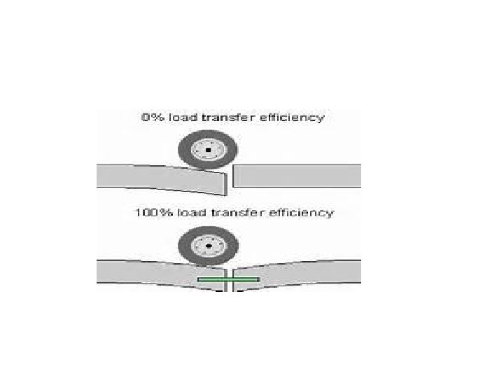
Types of deflectometer • FWD data can also be used to calculate the degree of load transfer between adjacent concrete slabs, and to detect voids under slabs. • A Light Weight Deflectometer (LWD) is a portable falling weight deflectometer. It is used primarily to test insitu base and subgrade moduli during construction.
Cont. . , • A Heavy Weight Deflectometer (HWD) is a falling weight deflectometer that uses higher loads, used primarily for testing airport pavements. The HWD can apply a loading in the range of 30 -320 k. N, enabling it to simulate even the most extreme aircraft wheel load such as the Boeing 777, the Airbus 340 or 380. The HWD is highly versatile and can be used to test on both rigid, paver block and flexible pavements used on roads and airports • A Rolling Weight Deflectometer (RWD) is a deflectometer that can gather data at a much higher speed (as high as 55 mph) than the FWD. It is a specially designed tractor-trailer with laser measuring devices mounted on a beam under the trailer. Another advantage of the RWD over the FWD is that it can gather continuous deflection data as opposed to discrete deflection data collected by the FWD.
Evaluation of load transfer efficiency of rigid pavement • By FWD • Location of height of fall=close to joints of pavement slab • Deflection measured close to the joint =load transfer efficiency of the joint • Due to application of load close to the joint both adjacent slab deflect by same amount joint efficiency =100%