PAT 303 HIGHWAY AND TRAFFIC TECHNOLOGY TRAFFIC SIGNAL


 Progressive Movements • Where it is desirable to install a signal to maintain")


 Traffic Signal Phases • The portion of a signal cycle time allocated to")


 of a particular movement is governed by several factors:")
 Saturation")


- Slides: 33
PAT 303 HIGHWAY AND TRAFFIC TECHNOLOGY TRAFFIC SIGNAL CONTROL SYSTEM Prepared By : Madam Liyana Ahmad Sofri
TRAFFIC SYSTEM SIGNAL CONTROL • Traffic signal - all mechanical or electrical–controlled devices used to control, direct, or warn drivers or pedestrians
To Provide Right–of–way To Vehicles On Each Approach To Increase Traffic Handling Performance Reduced Traffic Delay Main Function Of An Installation Of A Traffic Light/Signal At An Intersection Is Reduced Traffic Conflict Points For Efficient Traffic Movement Safety
• Conflict points - points at which there are possibilities of two or more vehicles collide if allowed to move simultaneously.
TRAFFIC SIGNALS Advantages • Provide orderly traffic movement through appropriate assignment of right-of-way. • Provide for the progressive flow of a platoon of traffic along a given route. • Interrupt heavy traffic at intervals to allow pedestrians and cross-street traffic to cross or to enter the main street flow. • Increase the traffic-handling ability of a junction. • Reduce number of conflict point, i. e. , to reduce frequency of occurrence of certain types of accidents
Disadvantages • Excessive delay for motorists and pedestrians, particularly during off–peak periods. • Increased accident frequency (i. e. , rear–end–collisions). • Disregard of signal indications.
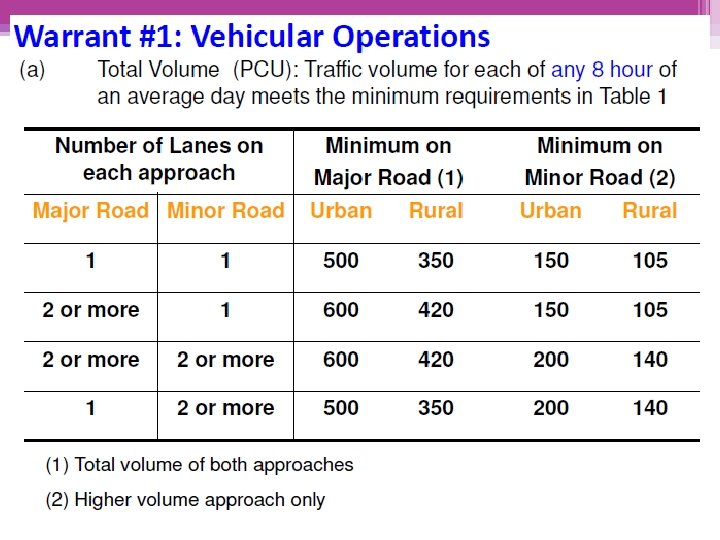
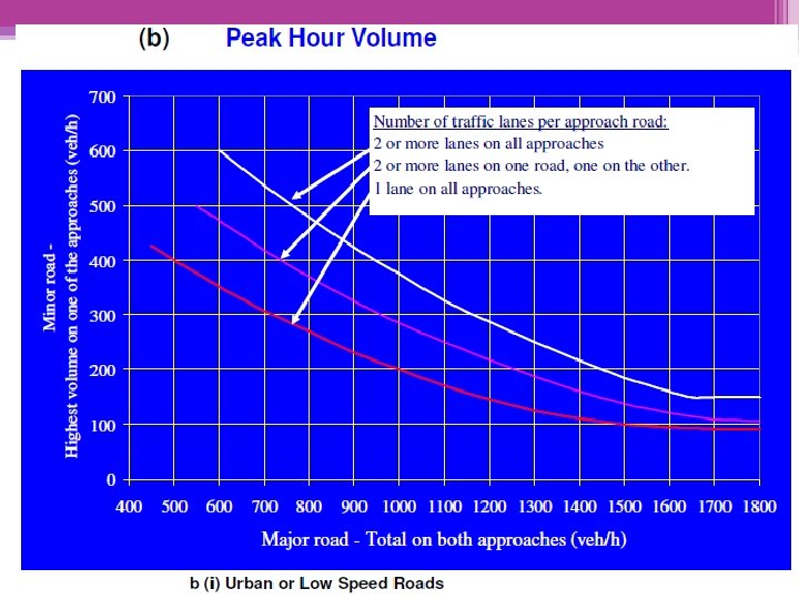
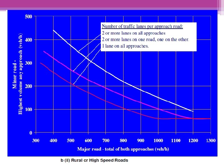
Warrant #1 – Vehicle Operations Installation of a traffic signal is warranted if one or more requirements specified in any of the warrants are satisfied. WARRANT FOR THE INSTALLATION OF A TRAFFIC SIGNAL SYSTEM Warrant #3 – Accidents Record. Warrant #2 – Pedestrian Safety
c) Progressive Movements • Where it is desirable to install a signal to maintain a proper grouping or platooning of vehicles and regulate group speed even though the junction does not satisfy other warrants for signalisation.
Total traffic on major road ≥ 600 veh/hour or where there is a raised median island 1. 2 m or more in width, 1, 000 or more veh/hour Warrant #2: Pedestrian Safety 150 or more pedestrian/hour crossing the road
Warrant #3: Accident Record The requirements for signalisation are satisfied when (based on at least a period of 3 years): • 1) There exist a record of 5 of more accidents in a year. Accidents types susceptible to correction by traffic signal control. • 2) There exist a volume of vehicular and pedestrian traffic not less than 80% of the requirements specified in warrants 1 and 2. • 3) The signal installation will not seriously disrupt progressive traffic flow • 4) Other methods found not effective to reduce accidents
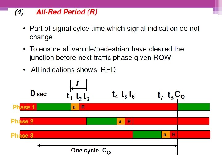
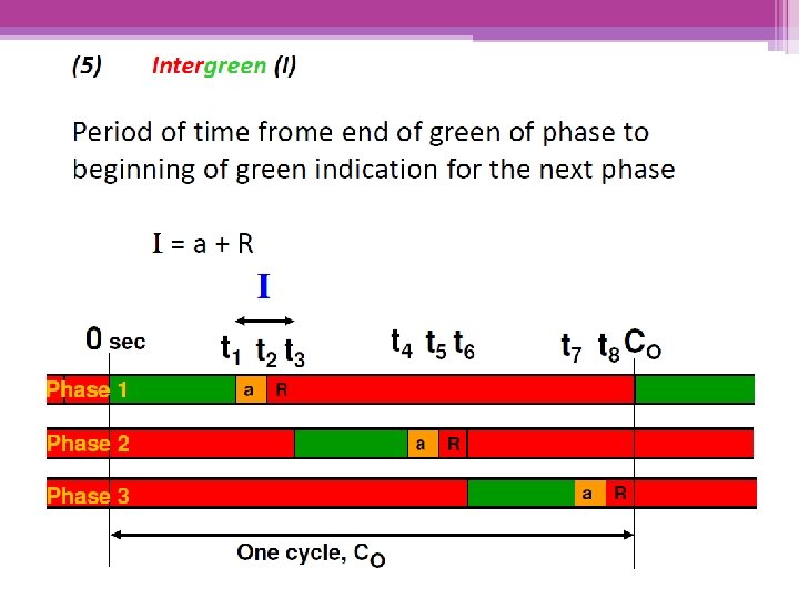
TERMINOLOGY & DEFINITIONS
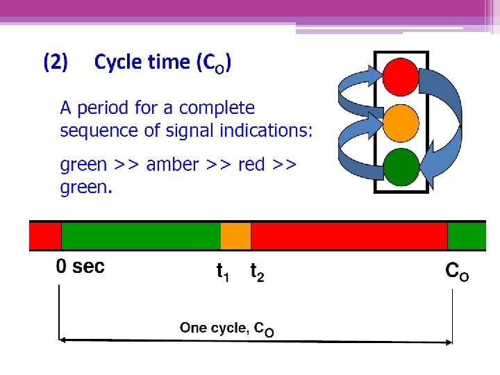
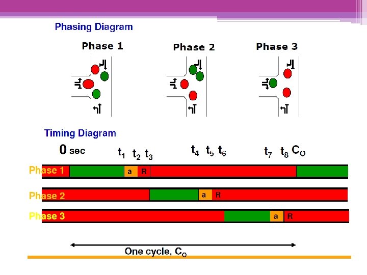
3) Traffic Signal Phases • The portion of a signal cycle time allocated to any single combination of one or more traffic movements simultaneously receiving the right-of way during one or more intervals. • Phase Sequence: • A predetermined order in which the phases of a cycle occur.
TYPES OF TRAFFIC SIGNAL Pre-timed or Fixed Time Vehicle-actuated Traffic Adjusted
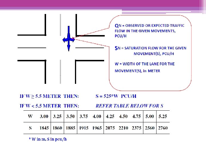
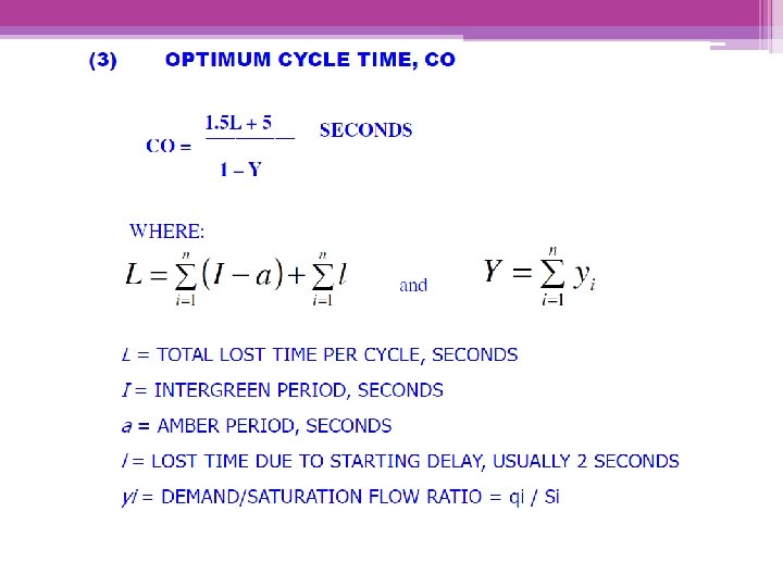
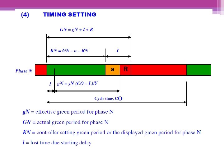
ELEMENTS TO CONSIDER IN THE DESIGN OF A TRAFFIC SIGNAL CONTROL SYSTEM Selection Of Traffic Phases Optimum Cycle Time, Co Saturation Flow, S Timing Setting
1. SELECTION OF TRAFFIC PHASES Minimum number of phase: 2 BUT, need to consider the needs to provide separate right-turn phase based on these criteria: • • 1. Traffic Volume 2. Delay 3. Accident record 4. Intersection geometry
GENERAL GUIDELINE FOR PROVISION OF SEPARATE RIGHT–TURNING PHASES: • Traffic Volume • i. Product of right–turning traffic volume and through volume of the conflicting direction ≥ 50, 000; or • ii. Total right –turning traffic ≥ 100 veh/h during peak hour; or • iii. Number of right–turning vehicles left in queue ≥ 2 veh/cycle at the end of green period. • Traffic Delay • i. Average delay to the right–turning vehicles ≥ 35 sec/veh. • Accidents involving right–turning vehicles • i. 4 or more accidents/year or 6 or more accidents for a period of 2 years on one particular approach; or • ii. 6 or more accidents/year or 10 or more accidents for a period of 2 years on both opposing approaches.
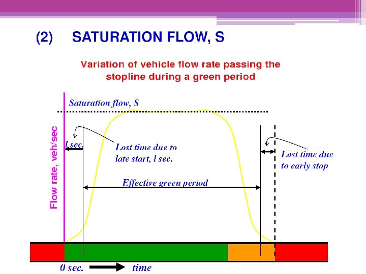
The actual saturation flow (S) of a particular movement is governed by several factors: Percentage of right–turning traffic ( FR ) Percentage of left–turning traffic ( FL ) Turning radius ( FT ) Gradient ( FG )
Therefore, S must be corrected to take account of the effects: • (i) Saturation flow for mixed movements lane: • S’ = S x FR x FL x FG pcu/h • (ii) Saturation flow for exclusive turning lane: • S’ = S x FT x FG pcu/h FR, FL, FT, and FG can be obtained from the respective Tables given.
DESIGN Step 1 - Identify Traffic STEPS Flow Volumes • including turning movements. Step 2 -Identify Junction Layout, Geometry and Site Characteristics Lane • It may be necessary, if revealed in Step 4 or Step 7, to modify the layout to cater for turning movements, pedestrians or to enhance capacity and/or safety. Step 3 - Identify Signal Phasing Step 4 - Check Turning Movements and Pedestrians • Adequate provision for turning movements and pedestrians should be checked.
Step 5 - Estimate Saturation Flows • The saturation flows for approaches/movements are identified. various Step 6 - Compute Y, L • The lost times, flow factors and sum of the critical flow factors are computed. Step 7 - Compute Reserve Capacity • If this is not satisfactory, then it may be necessary to go back to Step 2, modify data and layouts and recalculate. Step 8 - Compute Co, Cm, and Cp. • The optimum, minimum and practical cycle times for operating the junction are then computed for further analysis, if necessary.
Step 9 - Select C • It is then necessary to select a cycle time for operating the intersection. Step 10 - Compute Green Times, Degree of Saturation • The green times of the various phases are then computed. • Degree of saturation may be computed as well if detailed analysis of signal operation is required. Step 11 – Determination of Signal Setting • Calculate effective green and actual green for overall and each phase Step 12 – Draw timing diagram • Check should confirm with C used.