PAT 205 BUILDING SERVICES I FACULTY OF ENGINEERING

PAT 205: BUILDING SERVICES I FACULTY OF ENGINEERING TECHNOLGY ACADEMIC SESSION 2016/2017 Dr Fazdliel Aswad Ibrahim

Subtopic: LIGHT, LIGHTING SYSTEM AND DESIGN

ARTIFICIAL LIGHTING Content Outline INTRODUCTION LAMP LUMINAIRES LIGHTING CONTROL LIGHTING SYSTEM DESIGN 3

ARTIFICIAL LIGHTING • • Artificial light sources are other sources of light which developed to compensate for or assist the natural light. Thousand of lamps are made for diverse applications. However, lighting fixtures design supposedly address physical size, texture, shape, colour and performance. Four major classes of artificial lighting (based on operating principle): Incandescent lamps: Convert electrical energy into heat at a temperature that cause the filament of the lamp to become incandescent (red or white hot). INTRODUCTION Fluorescent lamps: Contain mercury vapour. When proper voltage is applied, electric arc produced between the opposing electrodes, generating some visible, but most invisible, UV radiation. The UV excites the phosphor coating on the inside of the bulb, then emits visible light. High-intensity discharge (HID): Produce high intensity light within an inner arc tube contained in an outer bulb. The metallic gas within the arc tube may be mercury, sodium, or a combination of other metallic vapour. The outer bulb may be clear or coated with phosphor. Mercury vapour, metal halide, and high-pressure sodium lamps are all classified as HID light sources. Miscellaneous lamps: Wide variety of lamps operating on different principles with limited application in the building but have a potential to breakthrough in the technology advance. E. g. : short-arc lamps, low-pressure sodium 4 lamps (LPS), electroluminescent lamps and electrode-less lamps.

ARTIFICIAL LIGHTING • • Light can be available whenever it is required e. g. outside of daylight hours. Light can be provided wherever it is required e. g. in areas far from the building envelope. Light can be provided however it is required i. e. in any quantity and with any distribution. This can be tailored to provide a variety of requirements e. g. task lighting, display lighting, general ambient lighting. The light provided is stable in output, unlike daylight, so where precise control is required of light quantity and quality e. g. colour, this can be guaranteed with an artificial system. INTRODUCTION 5

ARTIFICIAL LIGHTING Luminous Efficacy PROPERTIES OF LAMPS Color Temperature Luminous Efficacy • expressed in two purposes: • When the operation of lamp is fails (filament cutoff). • When the luminous efficacy of a lamp decreases with time and for a discharge lamp it may fall by as much 50% before the lamps fail. • This is a measurement of warmth or coolness provided by the lamp. • Refers to the color of a blackbody radiator at a given absolute temperature. • Unit: Kelvins. • A blackbody radiator changes color as its temperature increases (first to red, then to orange, yellow, white, and finally bluish white at the highest temperature). • Colour temperature higher than 4, 000 K are experienced as ‘cold light’, while colour temperature lower than 3, 000 K are experienced as ‘warm light. • The correlated colour temperature (CCT) of a light source is the absolute temperature of a perfect radiator when the colour appearance of the radiator best matches that of the light source. 6

ARTIFICIAL LIGHTING Color Rendering PROPERTIES OF LAMPS • Colour rendering is the ability of a light source to reveal the colour appearance of surfaces. • The colour appearance of a surface is affected by the quality of light from the source. • This ability is measured by comparing the appearance of objects under the light source with their appearance under a reference source such as daylight. • The same colours, viewed with different light sources, can appear very different. • The most widely adopted method of indicating colour rendering performance of lamps is the CIE colour rendering index (C. R. I. ). • The CRI is a 1– 100 scale that measures a light source's ability to render colors the same way sunlight does. • The top value of the CRI scale (100) is based on illumination by a 100 -watt incandescent light bulb. A light source with a CRI of 80 or higher is considered acceptable for most indoor residential applications. 7

ARTIFICIAL LIGHTING TYPES OF LAMPS Incandescent Lamps Discharge Lamps Tungsten Filament Low-intensity Discharge Lamps Tungsten Halogen High-intensity Discharge Lamps Solid State Lamps Light Emitting Diodes 8

ARTIFICIAL LIGHTING Incandescent Lamps Tungsten Filament Tungsten Halogen TYPES OF LAMPS TUNGSTEN FILAMENT LAMPS (GLS) TUNGSTEN HALOGEN (TH) LAMPS • Low cost and simple installation • More efficient • Short life (1000 hrs) • 2 -3 x lamp life • Low luminous efficacy • More expensive • High electrical running cost • High CRI • Only about 5% of the electrical energy is converted to visible light • High running cost, very hot operation 9

ARTIFICIAL LIGHTING Discharge Lamps Low-intensity Discharge Lamps High-intensity Discharge Lamps • produce light by passing an electric current through a gas or vapour that emits light when ionized by the current. • ballast supplies voltage to the lamp’s electrodes enhance electron emission. • gas or vapor is an electrical insulator, but it will be a conductor when a high voltage charged on him or upon heated. TYPES OF LAMPS Tubular Fluorescent Lamps (MCF) • Common MCF lamp is a form of gas discharge using mercury vapour at low pressure Low Intensity Discharge Lamps Compact Fluorescent Lamps (CFL) • CFL produce light in the same manner as MCF but better color rendering, lamp life, high efficacy • High light quality and low energy lighting in homes 10

ARTIFICIAL LIGHTING Discharge Lamps High Pressure Mercury Low-intensity Vapor Lamp Discharge TYPES OF LAMPS Metal Halide lamps High Intensity Discharge Lamps High Pressure Sodium Lamps Low Pressure Sodium Lamps Light is produced by • Lamps an electric discharge through gaseous High-intensity mercury Mercury vapor lamp with other metal compounds (i. e. halides) added to the arc tube • Light is produced in a high pressure sodium lamp by an electric discharge through combination of vapor of mercury and sodium • Provide most energy efficient outdoor lighting but poor CRI Lowest efficacy, rapid • • There are four basic types • depreciation, of lumen lamps considered as HID low CRI light sources: • high-pressure mercury vapor lamps • 24, 000 hrs lamp life • metal-halide lamps • high-pressure sodium lamps and • Low pressure sodium lamps. Better luminous efficacy, CRI • Lower CRI but longer life time • Require up to 10 minutes starting and have to cool before they can start • Discharge Lamps 11

ARTIFICIAL LIGHTING Solid State Lamps Light Emitting Diodes TYPES OF LAMPS • LEDs are solid-state semiconductor devices that convert electrical energy directly into light. • LEDs can be extremely small and durable; some LEDs can provide much longer lamp life than other sources. • have very long lamp lives and good efficacies. • can generate red, yellow, green, blue or white light, have a life up to 100, 000 hours, and are widely used in traffic signals and for decorative purposes. • Very efficient light production • Wide selection of standard ranges • Can be switched and dimmed as required • Very long service life • Good to very good colour rendering • Very good production of coloured light • Use: LEDs can be used for both functional and decorative lighting in indoor and outdoor locations. 12

ARTIFICIAL LIGHTING General • commonly called "lighting fixtures" or "fittings” hold one or more lamps (light sources) together with optical and mechanical components. • Is a unit consists: • Lamps • lamp sockets • Ballasts • reflective material • lenses, refractors, or louvers • housing LUMINAIRES Functions • connecting the lamp to the electricity supply • controlling the light emitted by the lamp • protecting the lamp from a hostile environment • providing a fixture of satisfactory appearance (to realise a lighting concept which fulfils the visual task) 13

ARTIFICIAL LIGHTING Reflector • A device, usually of coated metal or plastic, that is a high reflectance and is shaped to redirect the light emitted by the lamp Diffusers • Light control elements that scatter (redirect) incident light in many directions. • This scattering can take place in the material, such as in bulk diffusers like white plastic, or on the surface as in etched or sandblasted glass. • Used to spread light and, since scattering destroy optical images, obscure the interior of luminaries, suppress lamp images, and reduce high illuminance by increasing the area over which light leaves a luminaire. LUMINAIRES Shades, Blades, Louvers & Baffles • Shades and shields are opaque or translucent materials shaped to reduce or eliminate the direct view of the lamp from outside the luminaire • Blades, usually opaque and highly reflective, can be shaped and positioned to eliminate the direct view of the lamp from certain directions outside the luminaire and to control the direction from which the light leaves. • If arranged in a rectangular grid, producing cells, they are called louvers. If arranged linearly they are called baffles. Louvers and baffles often are made of specularly reflecting metal, though some are of coated plastic. Refrafctors • Light control devices that take advantage of the change in direction that light undergoes as it passes through the boundary of materials of differing optical density (index of refraction), such as air to glass or air to plastic. Classification • Luminaires are classified by the Commission International de L’Eclairage (CIE) according to the percentage of light output (light distribution) above and below the horizontal 14

ARTIFICIAL LIGHTING Lighting Control Purpose • Fulfil certain building regulation for energy savings. • Control lighting installation in order to optimize use of daylight. • Reduce energy when a space is unoccupied. • Facilitate the activities. Types • Switching – to turn on-off. • Dimming – techniques and equipment to control the light source, depending on the color of the light generated. 15

ARTIFICIAL LIGHTING ON-OFF control • Simplest way to turn lights ON or OFF. • To be effective, the lighting systems must be designed as well so that the switching system enables a single light or a row of lights can be made flexible. Panel switches must be placed at appropriate locations and clearly marked. Switched Method Automatic control • • Motion sensor Occupancy sensor Photo Sensor Timers Control Processor • Micro computer based control systems have become increasingly popular, more durable and inexpensive. It depends on the computer or a processor dedicated to control some or all of the building facilities. • Complex decisions can be made from time to time based on the exact conditions of building operations and systems controlled by computers. • The control programs could be improved and adjusted to the building and can be modified in accordance with changing conditions. • It is possible to interface between a building energy management system (BEMS) and a lighting energy management system (LEMS) in order to provide certain control commands from the BEMS to the lighting. 16

ARTIFICIAL LIGHTING Lighting System Design Requirements • Comply the level of illumination (IES Code, CIBSE, JKR). • Within budget, code, other constraints. • Environmentally responsible. • Respond to architectural and interor design. • Good CRI • Able to control the light. Types • General lighting • Localised lighting • Local lighting 17

ARTIFICIAL LIGHTING General Lighting • provide an approximately uniform illuminance over the whole working plane. • luminaires are normally arranged in a regular layout, and the appearance of the installation is usually tidy but may be rather bland. • General lighting is simple to plan using the lumen method and requires no coordination with task locations. • The greatest advantage of such systems is that they permit flexibility of task location. • The major disadvantage of general lighting systems is that energy may be wasted in illuminating the whole area to the level needed for the most critical tasks. • Energy could be saved by providing the necessary illuminance over only the task areas, and using a lower ambient level for circulation and other non-critical tasks. A general lighting system employs a regular array of luminaires to provide a uniform illuminance across the working plane 18

ARTIFICIAL LIGHTING Localised Lighting • Localised lighting systems employ an arrangement of luminaires designed to provide the required maintained illuminance on work areas together with a lower illuminance for the other areas. • The average illuminance on the other areas should not be less than one-third of the average illuminance over the work areas. • The lighting layout must be coordinated with the task positions and orientation. • The system can be inflexible, and information on plant and furniture layout is essential at the design stage. • Changes in the work layout can seriously impair a localised system, although uplighters and other easily relocatable systems or energy management controls can overcome these problems. • Localised systems normally consume less energy than general lighting systems unless a high proportion of the area is occupied by workstations. This should be confirmed by calculations. • Maintenance of localised systems can be more critical than with general lighting systems. localised lighting system uses luminaires located adjacent to the workstations to provide the required task illuminance. The necessary ambient illuminance in the surrounding areas is provided by additional luminaires if required 19

ARTIFICIAL LIGHTING Local Lighting • provides illumination only over the small area occupied by the task and its immediate surroundings. • A general lighting system must be installed to provide sufficient ambient illumination for circulation and non-critical tasks. • This is then supplemented by the local lighting system to achieve the necessary design maintained illuminance over the task areas. • The general surround average illuminance should not be less than one-third of the average task illuminance. • Local lighting can be a very efficient method of providing adequate task illumination, particularly where high illuminances are necessary or flexible directional lighting is required. • Local lighting is frequently provided by luminaires mounted at the work place in offices and factories. • Local lighting must be positioned to minimise shadows, veiling reflections and glare. • Although local luminaires allow efficient utilisation of emitted light, the lower wattage lamp circuits will be less efficient and the luminaires can be expensive. • Most local lighting systems are accessible and often adjustable. This increases wear and tear and hence maintenance costs, but the system provides individual control, which is often favoured by those working in the area. • Both local and localised lighting offer scope for switch control of individual luminaires that can be off when not required, but sufficient ambient illumination must be provided at all relevant times. A local lighting system employs a general lighting scheme to provide the ambient illuminance for the main area, with additional luminaires located at the workstations to provide the necessary task illuminance 20

ARTIFICIAL LIGHTING Illumination Requirements 21

ARTIFICIAL LIGHTING Design Process 22

ARTIFICIAL LIGHTING Lumen Method Design Dimension of Room PARAMETERS Mounting Height Room Index, K Surface Reflectance Utilization Factor, UF Maintenance Factor, MF Layout Space Height Ratio, SHR Unified Glare Rating, UGR Explanation & Example (pg. 19 – 55) 23

• This method is most suitable for interior lighting design , where a high proportion of light on the working plane is reflected by internal surfaces. • The lumen method is applicable to design of a uniform (general) lighting scheme in a space where flexibility of working locations or other activities is required. • The lumen method is applied only to square or rectangular rooms with a regular array luminaires as shown in Figure 4. 5.

Figure 4. 5: Spacing of Luminaires

Lighting Design Parameters There are several parameters that influence the design such as: a. Dimension • Identify the dimension of room such as length, width and the height of ceiling to determine the room area.

b. Mounting Height, hm • Is the distance between lamp fixture assembly level and work plane. (shown in Fig. 4. 6) • Usually the lamp fixture is recessed on the ceiling. • The work plane is between 0. 8 to 1 m from the floor. • The distance from the source to the working plane is very important as it is major determinant of the final illumination level. ceiling lamp hm hm desk floor Figure 4. 6: Mounting height (Hm)

c. Room Index, K • The room index is a number that describes the ratios of the room length, width and height. Lx. W • Formula K = Hm ሺL+ Wሻ • Where: L = Room Length, W = Room width Hm = Mounting height of luminaires (from working plane) • The result of this calculation will be a number usually between 0. 75 and 5. • Note: This formula for K is only valid when room length is less than 4 times the width or when the K value is greater then 0. 75.

d. Surface Reflectance • The room is considered to consist of three main surfaces: (a) The ceiling cavity, (30 – 70 %) (b) The walls, and (30 – 50%) (c) The floor cavity (or the horizontal working plane). (10 – 20%. ) • The effective reflectance of the above three surfaces affect the quantity of reflected light received by the working plane.

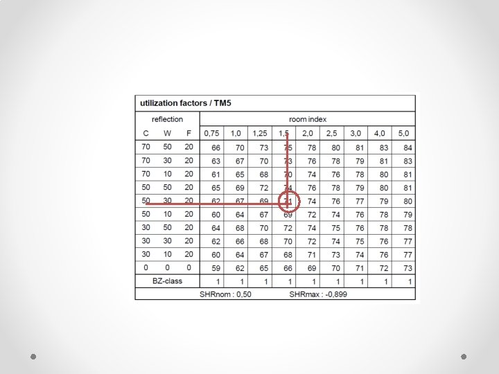
e. Utilization Factor • The Utilization Factor indicates which percentage of the light reaches the working surface. • The UF depends on the shape of the room (see room index) and on the reflection factors of reflecting surfaces. • Fig 4. 1 shown the UF table.

Figure 4. 7: UF table

Example: • Calculate the Utilization factor for a room with the following dimensions: Length 8 m; Width 6 m; Height 3 m; height of working plane 0. 8 m. The room reflectance is Ceiling 0. 5; Walls 0. 3 and Floor 0. 2.
 L W 8 6 R. I 1. 558")
Step 1: Calculate Room Index (K) L W 8 6 R. I 1. 558 say 1. 5 Hm L W 2. 2 8 6)

Step 2: Utilization factor value • Using the utilization factor table. • For the horizontal row select the reflectance that best describes the room. • For the vertical column select the room index value K as calculated above. • The utilization factor for this fitting in this room is where the row and column intersect. • From Table 5. 1 the Utilization factor can be read as 0. 71
 • Light loss factor (LLF) is the ratio of the")
f. Maintenance Factor (MF) • Light loss factor (LLF) is the ratio of the illuminance produced by the lighting installation at the some specified time to the illuminance produced by the same installation when new. LLF = LLMF x RSMF LLMF = Lamp Lumen maintenance factor. LMF = Luminaire maintenance factor. RSMF = Room surface maintenance factor. • The maintenance factor is based on how often the lights are cleaned and replaced. It takes into account such factors as decreased efficiency with age, accumulation of dust within the fitting itself and the depreciation of reflectance as walls and ceiling age. For convenience, it is usually given as three options; Good = 0. 70 Medium = 0. 65 Poor = 0. 55

Figure 4. 8: Typical lumen maintenance and lamp survival data

Figure 4. 9: Luminaire categories and a list of typical locations where the various environmental conditions may be found

Figure 4. 10: Typical changes in light output from a luminaire caused by dirt deposition, for a number of luminaire and environment categories

Figure 4. 11: Typical changes in the illuminance from an installation that occur with time due to dirt deposition on the room surfaces

Example: • Calculate the maintenance factor for an installation of a bare lamp batten luminaire equipped with fluorescent halo phosphor lamp. The lamp and luminaire will be installed inside the small office with the area 6 m 2. The luminaires are cleaned every 30 months, the lamps are replaced after 6000 hours and room surfaces are cleaned every 36 months.

Solution: MF @ LLF = LLMF x LSF x LMF x RSMF LLMF & LSF table (6000 hours) Therefore LLMF = 0. 8 LSF = 0. 99 Bare lamp battern, type A ; Office envi Normal ; 30 month (2. 5 years) therefore LMF = 0. 82 refer Small office, every 36 months (3 years); luminaire direct/ indirect; envi normal. therefore RSMF = 0. 79 So LLF = 0. 8 x 0. 99 x 0. 82 x 0. 79 = 0. 51

g. Layout • For uniform lighting patterns a regular arrangement of lights is desired. • Generally, for linear luminaries, keep the long luminaire parallel to the long room axis. • A diagonal luminaire arrangement can be distracting, and the order of room disjointed from order of light source. Number in Length = Total, �x LΤW Number in Width = Total, �x WΤL
 • Spacing to Mounting Height ratio (SHR or S/Hm)")
h. Space Height Ratio (SHR) • Spacing to Mounting Height ratio (SHR or S/Hm) is defined as the ratio of the distance between adjacent luminaires (centre to centre), to their height above the working plane. (as shown in Fig 4. 12) • If uniformity of illuminance is to be acceptable for general lighting, SHR should not exceed maximum spacing to height ratio (SHR MAX) of the given luminaire as quoted by the manufacturer, • Linear source Smax = 1. 5 x Hm • Point source Smax = 1. 0 x Hm
 (a)")
S/2 S S/2 Hm Working plane Floor S/2 S S (spacing between lamp) (a) Point Source (b) Linear source Figure 4. 12(a) & (b) : Ratio of space between luminaires (S) to their height above the working plane (Hm).
 • Indek silau ditentukan untuk memastikan jumlah lampu yang")
h. unified glare rating (ugr) • Indek silau ditentukan untuk memastikan jumlah lampu yang diperolehi tidak mengakibatkan silau pada permukaan ruang yang direkabentuk. Nilai had silau yang dicadangkan untuk pejabat ialah 19, pejabat lukisan 16 dan kerja industri kasar adalah 28.
 • The UGR method relates to glare from ceiling")
h. unified glare rating (UGR) • The UGR method relates to glare from ceiling fixtures that are placed in a regular pattern. • European standard EN 12461, Lighting of Indoor Work Places, contains a table in which the maximum allowed UGR value is prescribed per type of room and per type of activity. • The UGR method produces a scale figure: - below 13 no glare - 13 – 16 suited for accurate eye tasks - 16 – 19 suited for average eye tasks - 19 – 22 suited for moderate eye tasks - 22 – 28 suited for simple eye tasks above - 28 not suited for work lighting

Lumen Method Calculations �The lumen method is based on fundamental lighting calculations n F UF MF where N = number of luminaire E = average illuminance over the horizontal working plane A = area of the horizontal working plane n = number of lamps in each luminaire F = lighting design lumens per lamp, i. e. initial bare lamp luminous flux UF = utilisation factor for the horizontal working plane LLF @ MF = light loss factor

The steps required in using the Lumen Method of lighting design are as follows: 1. Select Required Illumination, E • Most countries have a set of minimum lighting levels for various tasks. The designer must determine what the minimum required illumination level is for their particular application. 2. Determine Received Flux, F Refer / given by manufacturer

3. Determine Mounting Height, Hm The distance from the source to the working plane is very important as it is a major determinant of the final illumination level. This is simply a function of the inverse square law. 4. Determine Room Index • The Room Index is required when using tables to find the utilisation factor. It is given by: L W RI Hm(L W) • Where L is the length of the room, W is its width and Hm is the mounting height above the work plane.

5. Determine room reflectance • Ceiling 30 – 70% • Wall 30 – 50 % • Floor 10 – 20 % 6. Determine utilisation factor • Refer table • Room reflectance • Room index
 • The maintenance factor is based on how")
7. Determine Maintenance Factor (MF/ LLF) • The maintenance factor is based on how often the lights are cleaned and replaced. It takes into account such factors as decreased efficiency with age, accumulation of dust within the fitting itself and the depreciation of reflectance as walls and ceiling age. For convenience, it is usually given as three options; • Good = 0. 70 • Medium = 0. 65 • Poor = 0. 55 8. Determine Number of luminaires • This if achieved using the following formula; n F UF MF

9. Proposed layout and check Spacing of Fixtures • Propose layout Number in width total N Number in length total N • Check spacing of layout Smax = 1. 5 x hm … linear source Smax = 1. 0 x hm …. . Point source or or Refer katalog/ table W L L W

Example • An office area measures 16 m x 8 m and is 2. 7 metres high. It is to be illuminated to an average value of 500 lux. 600 mm x 600 mm recessed luminaires, each containing 4 lamps are used. Each lamp has an output of 1400 lumens. Utilisation factor is 0. 5 and maintenance factor is 0. 75. Given SHR 1. 75. a. Calculate the number of luminaires required. b. Check a layout of the scheme indicating the spacing between luminaires.
 Step 1: Number of luminaire, N E – 500 lux A –")
Solution (a) Step 1: Number of luminaire, N E – 500 lux A – 16 x 8 = 128 m sq MF – 0. 75 UF – 0. 5 n F UF MF n – 4 lamps 500 128 F – 1400 lumens 4 1400 0. 5 0. 75 30
 Step 2: Layout W 8 Number in width total 30 4 L 16")
(b) Step 2: Layout W 8 Number in width total 30 4 L 16 Number in length total • Therefore layout 4 x 8 L 16 31 8 W 8
 Step 3: Check layout SH ratio = 1. 5 : 1. Therefore maxima")
(c) Step 3: Check layout SH ratio = 1. 5 : 1. Therefore maxima spacing, Sm = 1. 5 x Hm = 1. 5 x 2 = 3 m Length, S L 16 2 8 Width, S W 8 4 2

ARTIFICIAL LIGHTING THANK YOU 58
- Slides: 58