
PART TWO CONTD E O AKINYEMI Prep Course




























- Slides: 56
PART TWO- CONTD. E. O. AKINYEMI Prep. Course in Hydraulics
FLOW IN CONDUITS n Very often Engineers need to answer the following types of questions: n How are water depth and discharge in a conduit related? n How does the velocity in a conduit change as the amount of water carried by the conduit increases? Prep. Course in Hydraulics
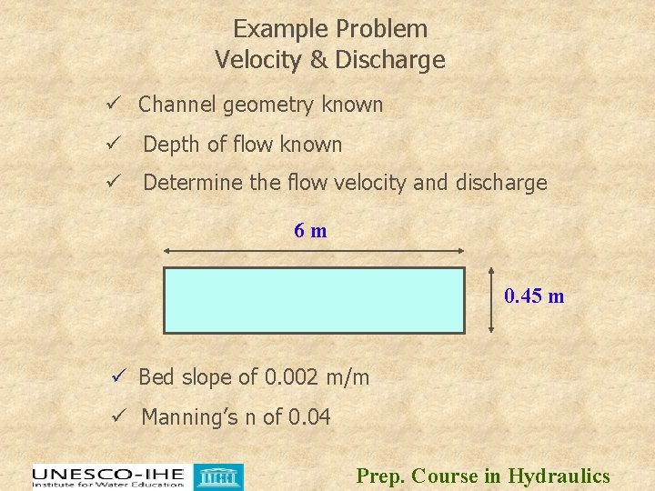
Example Problem Velocity & Discharge ü Channel geometry known ü Depth of flow known ü Determine the flow velocity and discharge 6 m 0. 45 m ü Bed slope of 0. 002 m/m ü Manning’s n of 0. 04 Prep. Course in Hydraulics
Solution n n n n q = va equation 1 v =(1. 0/n) R 2/3 S 1/2 (equation 2) R= a/P (equation 3) a = width x depth = 6 x 0. 45 m = 2. 7 m 2 P= 6 + 0. 45 m = 6. 9 m. R= 2. 7/6. 9 = 0. 39 m S = 0. 002 m/m (given) and n = 0. 04 (given) v = (1. 0/0. 04)(0. 39)2/3(0. 002)1/2 = 0. 6 m/s q = va=0. 6 x 2. 7= 1. 62 m 3/s Answer: the velocity is 0. 6 m/s and the discharge is 1. 6 cms Prep. Course in Hydraulics
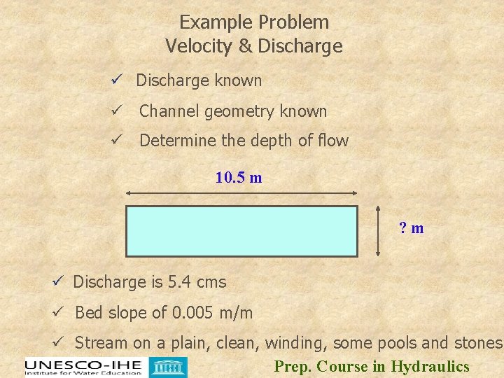
Example Problem Velocity & Discharge ü Discharge known ü Channel geometry known ü Determine the depth of flow 10. 5 m ? m ü Discharge is 5. 4 cms ü Bed slope of 0. 005 m/m ü Stream on a plain, clean, winding, some pools and stones Prep. Course in Hydraulics
Solution n n n q = va equation 1 v =(1. 0/n) R 2/3 S 1/2 (equation 2) R= a/P (equation 3) Guess a depth! Lets try 0. 6 m a = width x depth = 10. 5 x 0. 6 ft = 6. 3 m 2 P= 10. 5 + 0. 6 m = 11. 7 m. R= 6. 3/11. 7 = 0. 54 m S = 0. 005 m/m (given) n = 0. 033 to 0. 05 (Table 1) Consider deepest depth v = (1. 0/0. 05)(0. 54)2/3(0. 005)1/2 = 0. 93 m/s q = va=0. 93 x 6. 3= 5. 86 m 3/s or cms If the answer is <10% different from the target stop! Answer: The flow depth is about 0. 6 m for a discharge of 5. 4 cms Prep. Course in Hydraulics
Governing Principles Resistance to Flow in pipes n n Fluids in motion are subjected to various resistances, which are due to friction. Friction may occur between the fluid & the pipe work, but friction also occurs within the fluid as sliding between adjacent layers of fluid takes place. The friction within the fluid is due to the fluid’s viscosity. When fluids have a high viscosity, the speed of flow tends to be low, and resistance to flow becomes almost totally dependant on the viscosity of the fluid, this condition is known as ‘Laminar flow’. Prep. Course in Hydraulics
Governing Principles Resistance to Flow in pipes n How do you establish resistance losses? n Before the pipe losses can be established, the friction factor must be calculated. The friction factor will be dependant on the pipe size, inner roughness of the pipe, flow velocity and fluid viscosity. The flow condition, whether ‘Turbulent’ or not, will determine the method used to calculate the friction factor. The starting point must be to find the fluid’s viscosity. This will be the factor that has most effect on the pipe losses. Prep. Course in Hydraulics
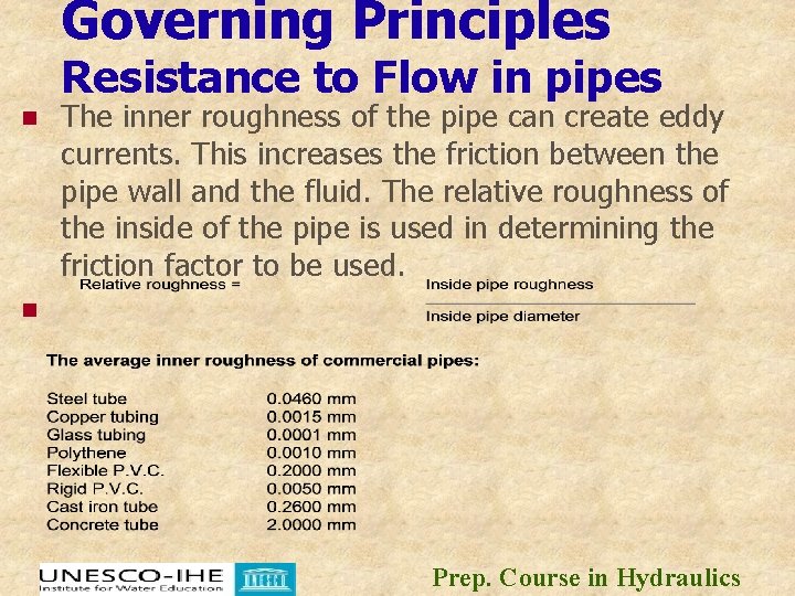
Governing Principles Resistance to Flow in pipes n n The inner roughness of the pipe can create eddy currents. This increases the friction between the pipe wall and the fluid. The relative roughness of the inside of the pipe is used in determining the friction factor to be used. Prep. Course in Hydraulics
General n n n For any channel of given roughness, cross section and slope, there exists one and only one water depth, called the normal depth d 0, at which the flow will be uniform. Given steady flow conditions, uniform flow will eventually be established in any channel which continues sufficiently far with constant slope and cross section. For steady uniform channel flow, channel slope, depth and velocity all remain constant along the channel. Prep. Course in Hydraulics
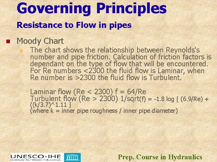
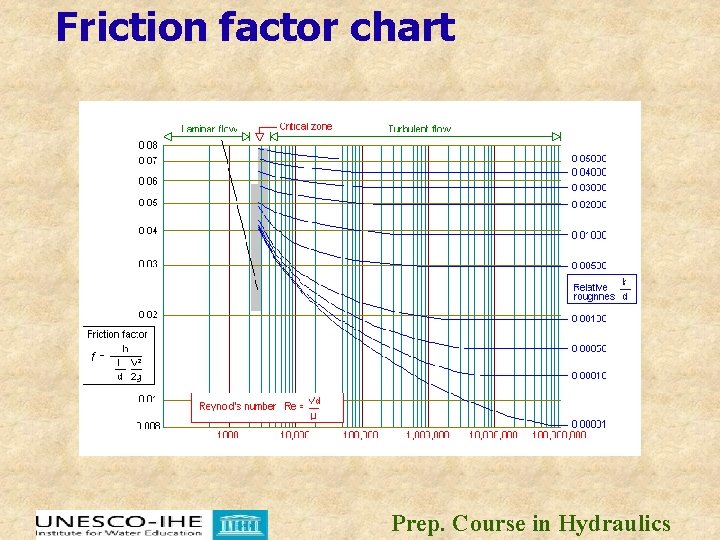
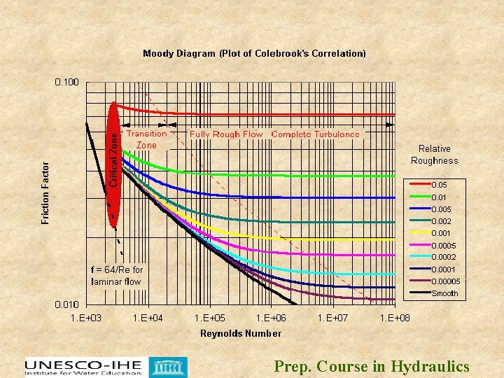
Governing Principles Resistance to Flow in pipes n Moody Chart n The chart shows the relationship between Reynolds's number and pipe friction. Calculation of friction factors is dependant on the type of flow that will be encountered. For Re numbers <2300 the fluid flow is Laminar, when Re number is >2300 the fluid flow is Turbulent. Laminar flow (Re < 2300) f = 64/Re Turbulent flow (Re > 2300) 1/sqrt(f) = -1. 8 log [ (6. 9/Re) + ((k/3. 7)^1. 11 ] (where k = inner pipe roughness / inner pipe diameter) Prep. Course in Hydraulics
Friction factor chart Prep. Course in Hydraulics
Resistance (velocity) Equations Prep. Course in Hydraulics
Velocity Relationships Prep. Course in Hydraulics
Governing Principles Resistance Equations n There are many equations that approximate the friction losses associated with the flow of a water through a given section. Commonly used methods include: n n Manning’s equation Chézy’s (Kutter’s) equation Hazen-Williams equation Darcy-Weisbach (Colebrook-White) equation Prep. Course in Hydraulics
Governing Principles Resistance Equations The lining material of the flow channel usually determines the flow resistance or roughness factor, C. However, the ultimate value of C may be a function of the channel shape, depth, and fluid velocity. Prep. Course in Hydraulics
Manning’s Equation n Manning’s equation is the most commonly used open channel flow equation. The roughness component, C, is typically assumed to be constant over the full range of flows and is represented by a Manning’s roughness value, n. These n-values have been experimentally determined for various materials and should not be used with fluids other than water. Manning’s equation is: Prep. Course in Hydraulics
Manning’s Equation n Given as Prep. Course in Hydraulics
Manning’s Equation Prep. Course in Hydraulics
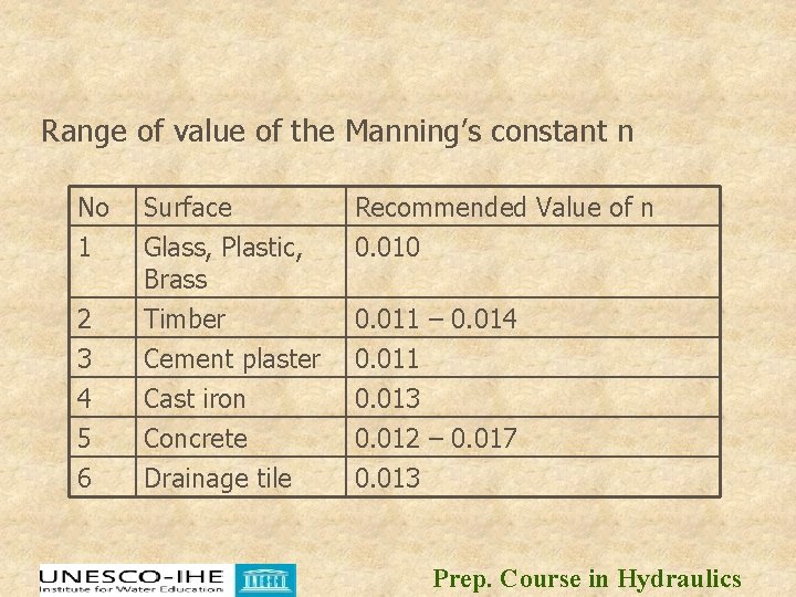
Range of value of the Manning’s constant n No 1 Recommended Value of n 0. 010 2 Surface Glass, Plastic, Brass Timber 3 4 5 6 Cement plaster Cast iron Concrete Drainage tile 0. 011 0. 013 0. 012 – 0. 017 0. 013 0. 011 – 0. 014 Prep. Course in Hydraulics
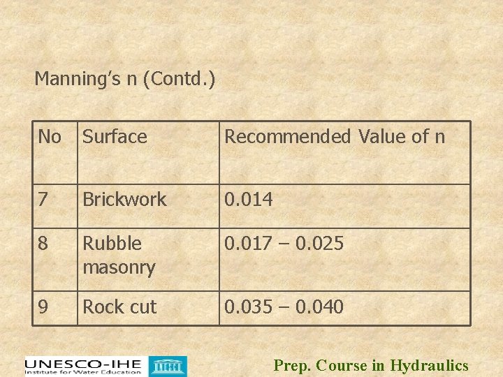
Manning’s n (Contd. ) No Surface Recommended Value of n 7 Brickwork 0. 014 8 Rubble masonry 0. 017 – 0. 025 9 Rock cut 0. 035 – 0. 040 Prep. Course in Hydraulics
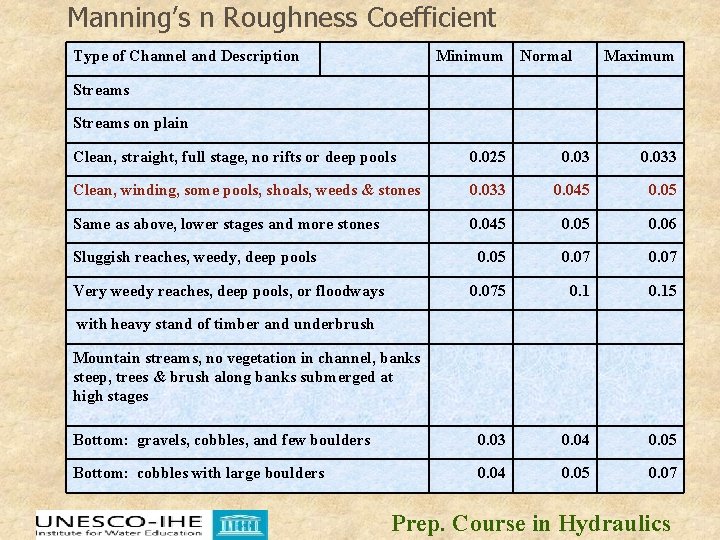
Manning’s n Roughness Coefficient Type of Channel and Description Minimum Normal Maximum Streams on plain Clean, straight, full stage, no rifts or deep pools 0. 025 0. 033 Clean, winding, some pools, shoals, weeds & stones 0. 033 0. 045 0. 05 Same as above, lower stages and more stones 0. 045 0. 06 0. 05 0. 075 0. 15 Bottom: gravels, cobbles, and few boulders 0. 03 0. 04 0. 05 Bottom: cobbles with large boulders 0. 04 0. 05 0. 07 Sluggish reaches, weedy, deep pools Very weedy reaches, deep pools, or floodways with heavy stand of timber and underbrush Mountain streams, no vegetation in channel, banks steep, trees & brush along banks submerged at high stages Prep. Course in Hydraulics
Applications of Manning’s Formula Prep. Course in Hydraulics
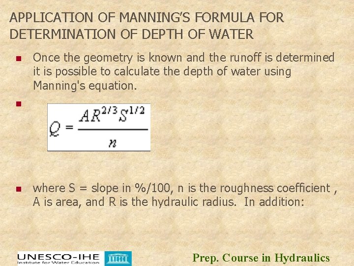
APPLICATION OF MANNING’S FORMULA FOR DETERMINATION OF DEPTH OF WATER n Once the geometry is known and the runoff is determined it is possible to calculate the depth of water using Manning's equation. n n where S = slope in %/100, n is the roughness coefficient , A is area, and R is the hydraulic radius. In addition: Prep. Course in Hydraulics
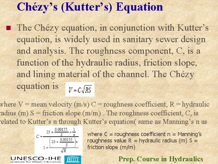
Chézy’s (Kutter’s) Equation n The Chézy equation, in conjunction with Kutter’s equation, is widely used in sanitary sewer design and analysis. The roughness component, C, is a function of the hydraulic radius, friction slope, and lining material of the channel. The Chézy equation is where V = mean velocity (m/s) C = roughness coefficient, R = hydraulic radius (m) S = friction slope (m/m). The roughness coefficient, C, is related to Kutter’s n through Kutter’s equation( same as Manning’s n as where C = roughness coefficient n = Manning’s roughness value R = hydraulic radius (m) S = friction slope (m/m) Prep. Course in Hydraulics
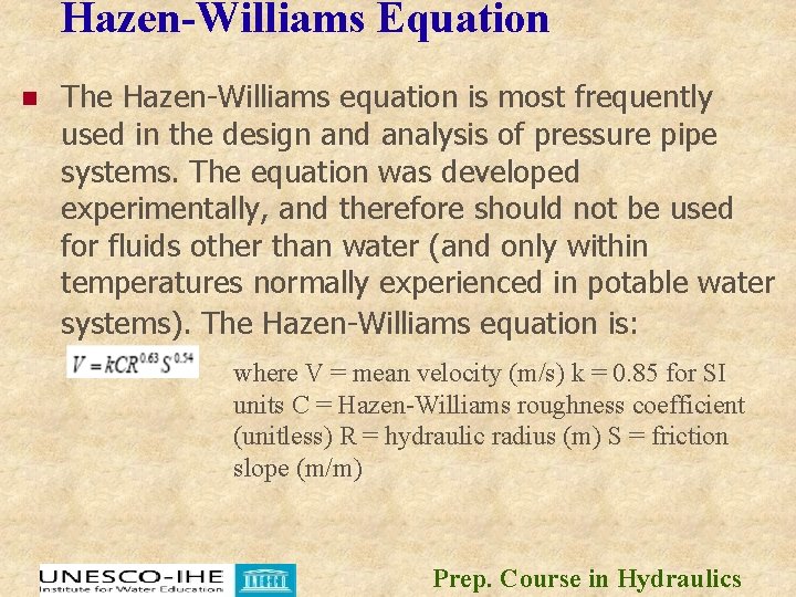
Hazen-Williams Equation n The Hazen-Williams equation is most frequently used in the design and analysis of pressure pipe systems. The equation was developed experimentally, and therefore should not be used for fluids other than water (and only within temperatures normally experienced in potable water systems). The Hazen-Williams equation is: where V = mean velocity (m/s) k = 0. 85 for SI units C = Hazen-Williams roughness coefficient (unitless) R = hydraulic radius (m) S = friction slope (m/m) Prep. Course in Hydraulics
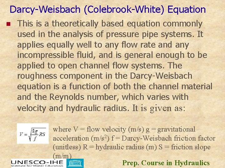
Darcy-Weisbach (Colebrook-White) Equation n This is a theoretically based equation commonly used in the analysis of pressure pipe systems. It applies equally well to any flow rate and any incompressible fluid, and is general enough to be applied to open channel flow systems. The roughness component in the Darcy-Weisbach equation is a function of both the channel material and the Reynolds number, which varies with velocity and hydraulic radius. It is given as: where V = flow velocity (m/s) g = gravitational acceleration (m/s 2) f = Darcy-Weisbach friction factor (unitless) R = hydraulic radius (m) S = friction slope (m/m) Prep. Course in Hydraulics
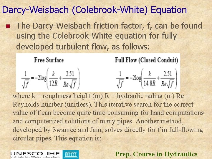
Darcy-Weisbach (Colebrook-White) Equation n The Darcy-Weisbach friction factor, f, can be found using the Colebrook-White equation for fully developed turbulent flow, as follows: where k = roughness height (m) R = hydraulic radius (m) Re = Reynolds number (unitless). This iterative search for the correct value of f can become quite time-consuming for hand computations and computerized solutions of many pipes. Another method, developed by Swamee and Jain, solves directly for f in full-flowing circular pipes. This equation is: Prep. Course in Hydraulics
Darcy-Weisbach (Colebrook-White) Equation where f = friction factor (unitless) k = roughness height (m) D = pipe diameter (m) Re = Reynolds number (unitless) Typical Roughness Factors Typical pipe roughness values for each of these methods are shown in the following Table. These values will vary depending on the manufacturer, workmanship, age, and other factors. For this reason, the following table should be used only as a guideline. Prep. Course in Hydraulics
Prep. Course in Hydraulics
Typical Roughness Coefficients Prep. Course in Hydraulics
Prep. Course in Hydraulics
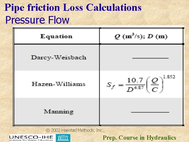
Pipe friction Loss Calculations n For pipes flowing full, many of the friction loss calculations are greatly simplified because the flow area, wetted perimeter, and hydraulic radius are all functions of pipe radius (or diameter). The following Table presents the pipe friction loss equations that are commonly used to design pressure pipe systems Prep. Course in Hydraulics
Pipe friction Loss Calculations Pressure Flow © 2002 Haestad Methods, Inc. , Prep. Course in Hydraulics
Pipe friction Loss Calculations Prep. Course in Hydraulics
Governing Principles Limiting Velocities n n When a drain is designed to flow at full capacity, it will be self-cleaning during dry weather flow if it is flowing at a minimum pipe full velocity of 1. 0 m/s. A drain that is to flow at partial capacity will be self-cleaning with a minimum flow velocity of 0. 8 m/s, when flowing at one third of full depth. The limiting velocity for concrete lined channels is 6 m/s to prevent damage to the concrete surface. Grass lined channels should have a limiting velocity of 2 m/s where there is a low flow pipe or stabilized low flow channel. Rock lining or other channel stabilization may be required for velocities greater than 1. 5 m/s. Many organizations adopt 6. 0 m/s as the safe maximum fullflow velocity in drains to minimize wear on the invert. Prep. Course in Hydraulics
References n n n n n 2002 Haestad Methods, Inc. , 37 Brookside Rd. , Waterbury, CT 06708. MIDUSS Version 2 Reference Manual - Chapter 8 Copyright Alan A. Smith Inc. B. S. Thandaveswara, Hydraulics Indian Institute of Technology Madras David Apsley, Hydraulics 3 Introduction to Open-Channel Flow Autumn 2009 A. P. Jarrett, Open Channel Design NCDENR February 23, 2007 W. H. Shayya, R. H. Mohtar and M. S. Baasiri; A Computer Model for the Hydraulic Analysis of Open Channel Cross. Sections Agricultural Sciences, 1 (1996) 57 -64 1996 Sultan Quaboos University Schwab et al. , 1966, USDA-SCS, 1972 b, and PA-DER, 1990). WEBSITES www. concrete-pipe. org Prep. Course in Hydraulics
n n “Flow in Pipes” Manual: Laminar and Turbulent Flow in Pipes. (http: //rothfus. cheme. cmu. edu/tlab/fluid 1. pdf ), 2001. Meadows, Michael E and Walski, Thomas M. Computer Applications in Hydraulic Engineering. 3 rd ed. Waterbury, CT: Haestad Methods, 1999. Mays, Larry W. Water Resources Engineering. 1 st ed. New York: John Wiley, 2001. HUMES; Pipes for drainage applications Prep. Course in Hydraulics
n n n Where to find more 1. Melvyn Kay, Practical Hydraulics, 2 nd edn, Spon 2006 (ISBN 978 -0 -203 -02297 -9) 2. Bird J, Engineering Mathematics, 5 th edn, Elsevier, 2007 (ISBN 978 -07506 -8555 -9) n Prep. Course in Hydraulics
WORKED EXAMPLE A concrete trapezoidal channel has a bottom width of 4 m and 45 degree side slopes. If the channel is on a 1 -percent slope and is flowing at a depth of 1 m throughout its length, how much flow is being carried (use Manning’s equation)? How much flow would the same channel carry if it were a rectangular channel 4 m wide? Solution Because the channel is flowing at the same depth throughout, we can assume that normal depth has been achieved (that is, the friction slope is equal to the channel slope). We will assume a Manning’s n of 0. 013 for concrete. From the trapezoidal geometry, we can easily calculate the area and wetted perimeter, and then the hydraulic radius, as follows: Prep. Course in Hydraulics
WORKED EXAMPLE A = (4 m × 1 m) + 2 × (0. 5 × 1 m) = 5. 00 m 2 Pw = 4 m + 2 × (1 m × 20. 5) = 6. 83 m R = A / Pw = 5. 00 m 2 / 6. 83 m = 0. 73 m Manning’s equation for velocity can then be solved. The discharge can be computed as V = (1. 00/0. 013) × 0. 732/3 × 0. 011/2 = 6. 25 m/s Q = V × A = 6. 25 m/s × 5. 00 m 2 = 31. 2 m 3/s To answer the second part of the question, we simply repeat the steps for a rectangular section shape. A = (4 m × 1 m) = 4 m 2 Pw = 4 m + 2 × (1 m) = 6 m R = 4 m 2 / 6 m = 0. 67 m V = (1. 00/0. 013) × 0. 672/3 × 0. 011/2 = 5. 87 m/s Q = 5. 87 m/s × 4 m 2 = 23. 5 m 3/s Prep. Course in Hydraulics
PRACTICE QUESTION n USE MANNING’S EQUATION TO ANALYZE AN EXISTING BRICK-IN-MORTAR (n=0. 015) triangular channel with 3 H: 1 V SIDE SLOPES AND A 0. 05 LONGITUDINAL SLOPE. THE CHANNEL IS INTENDED TO CARRY 0. 189 cms DURING A STORM EVENT. IF THE MAXIMUM DEPTH IN THE CHANNEL IS 0. 15 m, IS THE EXISTING DESGN ACCEPTABLE? n FOR EXAMPLES OF AVAILABLE TOOLS FOR SOLUTION OF THIS TYPE OF PROBLEM AND OTHER HYDRAULICS PROBLEMS CLICK HERE Prep. Course in Hydraulics
MORE WORKED EXAMPLES Prep. Course in Hydraulics
1. A rectangular channel 1. 5 m wide with a bed slope of 0. 0001 carries water to a depth of 1. 2 m. The channel has Manning’s n=0. 025. Calculate the rate of uniform flow in the channel. Soln: B=1. 5 m, y=1. 2 m, N=0. 025, Q=? Manning’s equation is Prep. Course in Hydraulics
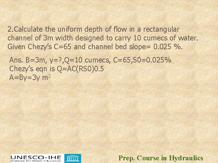
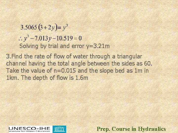
2. Calculate the uniform depth of flow in a rectangular channel of 3 m width designed to carry 10 cumecs of water. Given Chezy’s C=65 and channel bed slope= 0. 025 %. Ans. B=3 m, y=? , Q=10 cumecs, C=65, S 0=0. 025% Chezy’s eqn is Q=AC(RS 0)0. 5 A=By=3 y m 2 Prep. Course in Hydraulics
Substituting all values in chezy’s eqn Prep. Course in Hydraulics
Solving by trial and error y=3. 21 m 3. Find the rate of flow of water through a triangular channel having the total angle between the sides as 60. Take the value of n=0. 015 and the slope bed as 1 m in 1 km. The depth of flow is 1. 6 m Prep. Course in Hydraulics
Prep. Course in Hydraulics
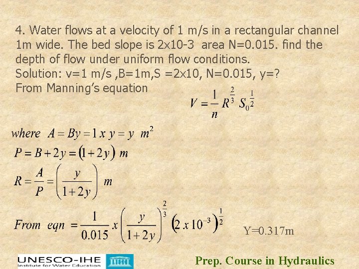
4. Water flows at a velocity of 1 m/s in a rectangular channel 1 m wide. The bed slope is 2 x 10 -3 area N=0. 015. find the depth of flow under uniform flow conditions. Solution: v=1 m/s , B=1 m, S =2 x 10, N=0. 015, y=? From Manning’s equation Y=0. 317 m Prep. Course in Hydraulics
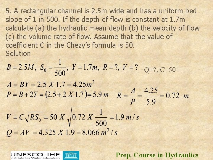
5. A rectangular channel is 2. 5 m wide and has a uniform bed slope of 1 in 500. If the depth of flow is constant at 1. 7 m calculate (a) the hydraulic mean depth (b) the velocity of flow (c) the volume rate of flow. Assume that the value of coefficient C in the Chezy’s formula is 50. Solution Q=? , C=50 Prep. Course in Hydraulics
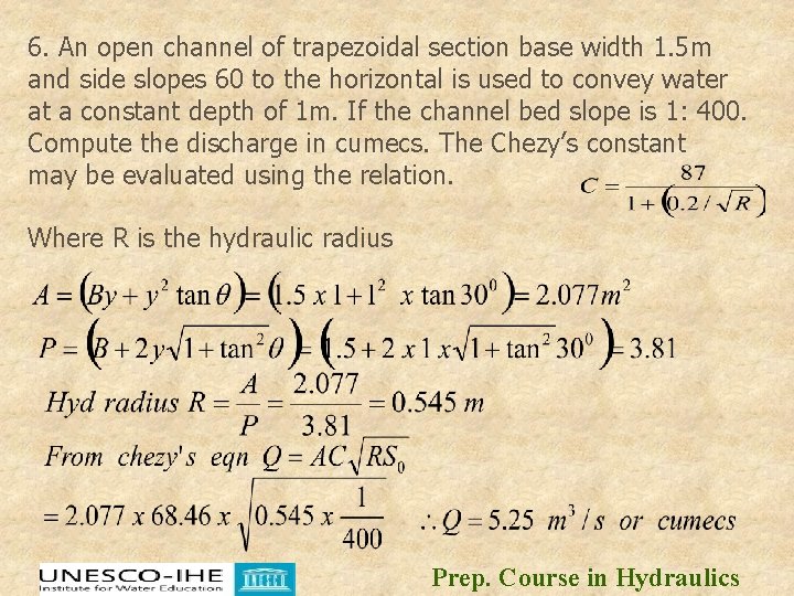
6. An open channel of trapezoidal section base width 1. 5 m and side slopes 60 to the horizontal is used to convey water at a constant depth of 1 m. If the channel bed slope is 1: 400. Compute the discharge in cumecs. The Chezy’s constant may be evaluated using the relation. Where R is the hydraulic radius Prep. Course in Hydraulics
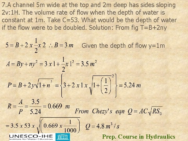
7. A channel 5 m wide at the top and 2 m deep has sides sloping 2 v: 1 H. The volume rate of flow when the depth of water is constant at 1 m. Take C=53. What would be the depth of water if the flow were to be doubled. Solution: From fig T=B+2 ny Given the depth of flow y=1 m Prep. Course in Hydraulics
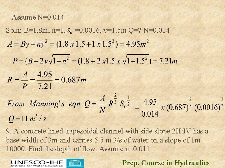
Solving by trial and error = 1. 6 m 8. A trapezoidal channel 1. 8 m wide at the bottom and having sides of slope 1: 1 is laid on a slope of 0. 0016. If the depth of the water is 1. 5 m. Find the rate of uniform flow Prep. Course in Hydraulics
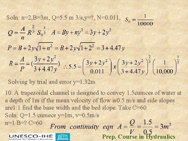
Assume N=0. 014 Soln: B=1. 8 m, n=1, =0. 0016, y=1. 5 m Q=? N=0. 014 9. A concrete lined trapezoidal channel with side slope 2 H: IV has a base width of 3 m and carries 5. 5 m 3/s of water on a slope of 1 m 10000. Find the depth of flow. Assume n=0. 011 Prep. Course in Hydraulics
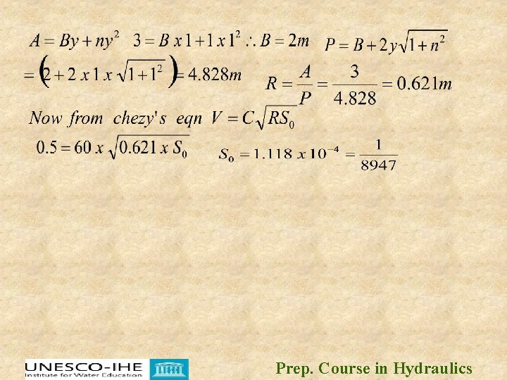
Soln: n=2, B=3 m, Q=5. 5 m 3/s, y=? , N=0. 011, Solving by trial and error y=1. 32 m 10. A trapezoidal channel is designed to convey 1. 5 cumces of water at a depth of 1 m if the mean velocity of flow is 0. 5 m/s and side slopes are 1: 1 find the base width and the bed slope. Take C=60 Soln: Q=1. 5 cumecs y=1 m, v=0. 5 m/s n=1 B=? C=60 Prep. Course in Hydraulics
Prep. Course in Hydraulics