Part Programming Turning Applications Steps in Part Programming


 3. Block and Words : Block - It is a group of")
 The words in the block are in following order : • •")

 Word")


 • Function: Moves to a new position")
 G 00 X 0 Y")
 • G 00 X")


 2. Secondary linear axes (U,")
-positive end of each axis")
 : V= DN/1000 2. Feed(fm) :")


 N 18 G 00 X 0")


 : V= DN/1000 2. Feed(fm) :")
 Feed per tooth (fz) : The")
 Feed per minute (fm) : The distance workpiece advances")
 : The thickness of material")
 XY plane selection (G 17) (ii)")
 : • Tool Pre setter- tool")

 47")
 48")


- Slides: 52
Part Programming Turning Applications
Steps in Part Programming Study of component drawing Deciding sequence of operations Identify machine tool Selecting cutting tool Deciding tool paths Determining Machining Parameters Preparing job and tool set-up plans Writing Part Program Testing Part Program Documentation of Part Program
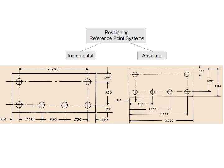
Terminology used in part programming 1. Absolute system : The co-ordinates are mentioned with respect to one reference point (datum) 2. Incremental System : The co-ordinates are mentioned with respect to the previous point (datum)
Terminology (Continued…) 3. Block and Words : Block - It is a group of words or coded instructions for the NC/CNC system to execute a particular movement Word - Each coded instruction
Terminology (Continued…) The words in the block are in following order : • • Sequence number (N) Preparatory functions (G) Dimensions (X, Y, Z, U, V, W and I, J, K) Feed functions (F) Spindle speed functions (S) Tool functions (T) Miscellaneous functions
Each line of program == 1 block Each block is composed of several instructions, or (words) Sequence and format of words: N 3 G 2 sequence no X+1. 4 Y+1. 4 Z+1. 4 I 1. 4 J 1. 4 K 1. 4 destination coordinates dist to center of circle preparatory function F 3. 2 S 4 T 4 M 2 tool feed rate spindle speed miscellaneous function
4. Formats Sequence of words in which information appears in a program (i) Word address format : Each word is identified by a letter (ii) Tab sequence format : Each word is separated from the other by ‘Tab’ character The words are identified by their respective positions in the block
Commonly used ‘G’ codes G 00 Rapid Positioning • Function: Moves to a new position as fast as possible. • Syntax: G 00 [axis words] • Example: • G 00 X 1. 2 Y 0. 3 ; Moves to (1. 2, 0. 3)
G 01 Linear Interpolation • Function: Moves to a new position linearly at some feed rate. • Syntax: G 01 [axis words] [optional feed word] • Example: • G 01 X 1. 2 Y 0. 3 F 3. 0 ; Moves to (1. 2, 0. 3) at 3 units/minute
G 02 CW circular interpolation (3 D) • Function: Moves to a new position in a clockwise circular arc. The arc center is specified with signed offsets from the start position or implicitly by the magnitude of the radius • Syntax 1: G 02 [two axis words (optional third)] [interpolation parameters] [optional feed word] • Syntax 2: G 02 [two axis words (optional third)] [radius word] [optional feed word]
Example 1: G 17 (plane XY specified for clarity) G 00 X 0 Y 0 (get into start position) G 02 X 2 Y 0 I 1 J 0 F 4
Example 2: • G 17 (plane XY specified for clarity) • G 00 X 0 Y 1 (get into start position) G 02 X 1 Y 0 R 1 F 4
Important GCodes G 00 Rapid Transverse G 01 Linear Interpolation G 02 Circular Interpolation, CW G 03 Circular Interpolation, CCW G 17 XY Plane, G 18 XZ Plane, G 19 YZ Plane G 20/G 70 Inch units G 21/G 71 Metric Units G 40 Cutter compensation cancel G 41 Cutter compensation left G 42 Cutter compensation right G 43 Tool length compensation (plus) G 44 Tool length compensation (minus) G 49 Tool length compensation cancel G 80 Cancel canned cycles G 81 Drilling cycle G 82 Counter boring cycle G 83 Deep hole drilling cycle G 90 Absolute positioning G 91 Incremental positioning
M-codes m 05 Spindle off
COORDINATE SYSTEMS • Right hand rule • Z axis align with the spindle - +Z moves away from the workpiece or the spindle. • X axis - Lathe: perpendicular to the spindle. Horizontal machine: parallel to the table. Vertical machine: +X points to the right.
Z axis : align with the spindle X axis : perpendicular to the spindle
Z axis : align with the spindle X axis : perpendicular to the spindle
Other Axes Designations 1. Rotational axes (A, B, C) 2. Secondary linear axes (U, V, W) 3. Incremental dimensions in Circular Interpolation (I, J, K)
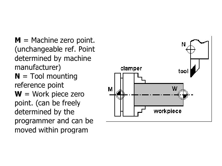
Zero points and Reference points 1. Machine zero point (M)-positive end of each axis travel range (Home position) 2. Blocking Point-Workpiece zero point (A) 3. Program zero point (W)-starting point of workpiece or like A 4. Start point (B)-first tool starts the machining process & is determined in program 5. Reference point (R)-floating point (determined by measuring system)
Cutting Process Parameter Selection 1. Cutting Speed (V) : V= DN/1000 2. Feed(fm) : fm= N x frev 3. Depth of Cut (t) : t=(D 1 -D 2)/2
Canned cycles • Multiple repetitive cycles • Consist of series of motions repeated no. of times e. g. drilling , boring , tapping • Drilling cycle consist of: 1. Rapid approach to workpiece 2. Drill at feed rate 3. Rapid return to initial position
Commonly used Canned cycles • G 74 -Stock removal cycle • G 78 -Multiple threading cycle • G 81 -Drilling cycle • G 85 -Boring cycle
General Structure of Turning Part Program N 0 N 1 N 2 N 3 N 4 N 5 N 6 N 7 . . . G 90 G 71 G 93 M 41 S 1500 G 94 G 28 U 0 W 0 M 06 T 0101 M 03 S 1500 G 00 X 50 Z 1 M 08 Absolute program mode Metric mode RPM range, Medium speed Feed rate (mm/min) Go to Home Position Tool change 01 with offset 01 Spindle ON Rapid tool positioning to (50, 1) Coolant ON
General Structure of Turning Part Program (Continued…. ) N 18 G 00 X 0 Z 1 Rapid tool positioning to (0, 1) N 19 G 28 U 0 W 0 Go to Home Position N 20 M 05 Spindle OFF N 21 M 09 Coolant OFF N 22 M 02 Program END N 23 M 30 END of tape and REWIND
Example 01 - Step Turning Operation N 7 G 00 X 42 Z 1 M 08 N 8 G 00 X 40 Z 1 N 9 G 74 X 30 Z-60 F 0. 2 D 1 N 10 G 00 X 32 Z 1 N 11 G 00 X 30 Z 1 N 12 G 74 X 20 Z-30 F 0. 2 D 1 N 13 G 00 X 22 Z 1 stock removal cycle
Example 02 -Clockwise Nose Turning N 7 G 00 X 42 Z-20 M 08 N 8 G 01 X 40 Z-20 F 0. 2 S 1500 N 9 G 02 X 0 Z 0 I-20 K 0 F 0. 2 S 1500 N 10 G 00 X 0 Z 2
Example 03 -Drilling & Boring Operation N 7 G 00 X 0 Z 1 M 08 N 8 G 00 X 0 Z 10 reference position of drill N 9 G 81 X 0 Z-30 F 0. 1 S 600 N 10 G 00 X 0 Z 1 N 11 G 00 X 12 Z 1 N 12 G 85 P 10 Q 10 U 0 W 0 F 0. 15 N 13 G 01 X 12 Z-30 F 0. 15 S 600 N 14 G 00 X 0 Z-30 N 15 G 00 X 0 Z 1
Example 04 -Threading Operation N 7 G 00 X 26 Z 1 M 08 N 8 G 78 X 19. 09256 Z-30 I 0 K 2. 4572 F 0. 2 D 1 A 60 N 9 G 00 X 26 Z 1 N 10 G 28 U 0 W 0
Example 03 - P. U. 2008 N 7 G 00 X 60 Z 1 M 08 N 8 G 74 X 40 Z-40 F 0. 25 D 1 N 9 G 02 X 60 Z-50 I 10 K 0 F 0. 35 N 10 G 00 X 62 Z 1 N 11 G 00 X 20 Z 0 N 12 G 01 X 40 Z-20 F 0. 35 S 400 N 13 G 00 X 42 Z 1
Example 03 - P. U. 2010 N 7 G 00 X 92 Z 1 M 08 N 8 G 74 X 80 Z-120 F 0. 25 D 1 N 9 G 00 X 82 Z 1 N 10 G 74 X 60 Z-70 F 0. 25 D 1 N 11 G 00 X 62 Z 1 N 12 G 00 X 40 Z 0 N 13 G 01 X 60 Z-20 F 0. 25 S 1500 N 14 G 00 X 62 Z-20 N 15 G 00 X 60 Z-70 N 16 G 03 X 80 Z-80 I 0 K-10 F 0. 25 N 17 G 00 X 82 Z-80
Part Programming Milling Applications
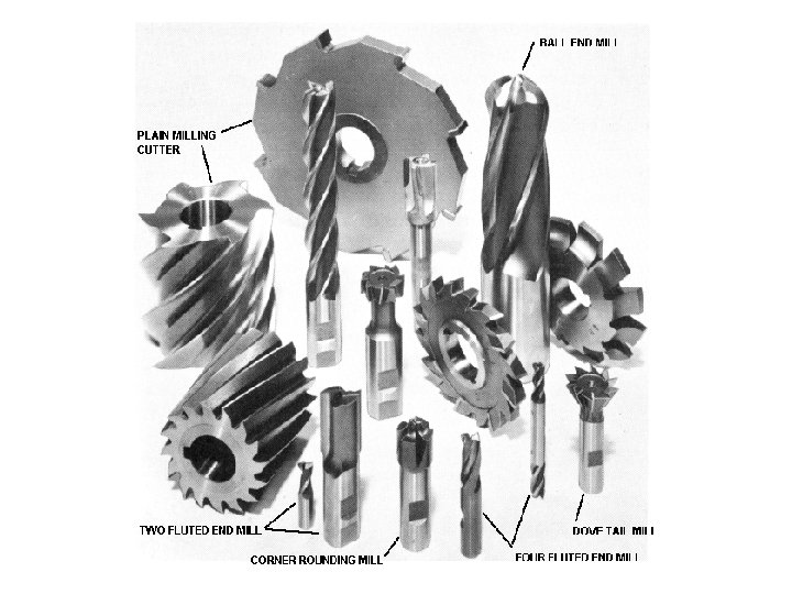
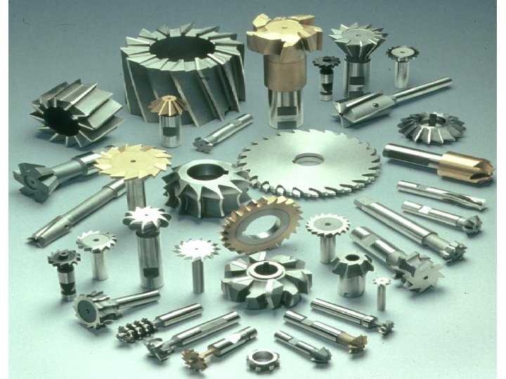
Milling Tools & Operations
Milling Machine Based on axis orientation : 1. Horizontal Milling Machine 2. Vertical Milling Machine
Z axis : align with the spindle X axis : perpendicular to the spindle
Cutting Process Parameter Selection 1. Cutting Speed (V) : V= DN/1000 2. Feed(fm) : The rate with which workpiece advances under the cutter
Cutting Process Parameter Selection Three Methods : (i) Feed per tooth (fz) : The distance workpiece advances in the time between engagement by two successive teeth (mm/tooth) (ii) Feed per cutter revolution (frev) : The distance workpiece advances in the time when the cutter turns through one complete revolution (mm/rev)
Cutting Process Parameter Selection (iii) Feed per minute (fm) : The distance workpiece advances in one minute (mm/min. ) All the above methods are related by the equation : fm= N x frev = fz x Z x N where, Z=No of teeth on the cutter
Cutting Process Parameter Selection 3. Depth of Cut (t) : The thickness of material removed in one pass of the workpiece under the cutter It is the perpendicular distance measured between original and final surface of workpiece
Common Preparatory Functions 1. Principal Plane Selection (i) XY plane selection (G 17) (ii) XZ plane selection (G 18) (iii) YZ plane selection (G 19) 2. Interpolations (i) Linear Interpolations (G 01) (ii) Circular Interpolations (G 02 & G 03) (iii) Helical Interpolations (G 32 & G 33)
Tool Compensations 1. Tool Length Compensations (G 43) : • Tool Pre setter- tool measuring device mechanical , electrical, optical • Tool Length offset ‘H’ • Tool register
Cutter Radius Compensations • For Contouring Operations Need to calculate tool cutter path by offsetting the contour by an amount equal to the radius of the cutter 1. Compensation OFF (G 40) 2. Cutter radius compensation left (G 41) 3. Cutter radius compensation right (G 42)
Cutter Compensation (G 41) 47
Cutter Compensation (G 41/G 42) 48
General Structure of Milling Part Program N 0 G 17 Principle XY Plane selection N 1 G 71 Metric mode N 2 G 40 CANCEL cutter radius compensation N 3 G 80 CANCEL canned cycle N 4 G 28 U 0 W 0 Incremental input , Tool axis pullout N 5 G 91 Z 0 Position to tool reference point N 6 X 0 Y 0 N 7 G 92 Reset origin point N 8 M 06 T 01 N 9 G 00 rapid travel to part zero N 10 G 90 X 0 Y 0 absolute programming N 11 G 43 Z 0 M 08 H 01 tool length compensation N 12 G 00 X_ Y_ M 03 S 500 spindle ON N 13 G 01 Z_ F 50 move tool downwards
General Structure of Milling Part Program. . . N 21 G 28 U 0 V 0 W 0 N 22 G 91 Z 0 N 23 G 28 N 24 G 91 X 0 Y 0 M 05 N 25 G 40 N 26 G 80 N 27 G 49 N 28 M 09 N 29 M 02 N 30 M 30 TOOL AXIS PULLOUT RETURN TOOL TO HOME & SPINDLE OFF CANCEL CUTTER RADIUS COMPENSATION CANCEL CANNED CYCLE CANCEL TOOL LENGTH COMPENSATION COOLANT OFF
Example: P. U. May 2007 N 11 G 43 Z 0 M 08 H 01 N 12 G 00 X 22 Y 22 M 03 S 500 N 13 G 01 Z-2 F 0. 1 N 14 G 42 X 25 D 06 N 15 G 01 X 90 N 16 Y 40 N 17 X 75 N 18 G 02 X 75 Y 55 I 00 J 7. 5 N 19 G 01 X 90 N 20 Y 80 N 21 G 03 X 75 Y 95 I-15 J 00 N 22 G 01 X 55 N 23 X 25 Y 75 N 24 Y 25 N 25 G 00 Z 00 TOOL LENGTH COMPENSATION CUTTER RADIUS COMPENSATION-RIGHT
Example: P. U. May 2009 N 11 G 43 Z 0 M 08 H 01 N 12 G 00 X 30 Y 30 M 03 S 500 N 13 G 01 Z-14 F 0. 1 N 14 G 00 Z 02 M 05 N 15 G 00 X 90 Y 30 M 03 S 500 N 16 G 01 Z-14 F 0. 1 N 17 G 00 Z 02 M 05 N 18 G 00 X 90 Y 70 M 03 S 500 N 19 G 01 Z-14 F 0. 1 N 20 G 00 Z 02 M 05 N 21 G 00 X 30 Y 70 M 03 S 500 N 22 G 01 Z-14 F 0. 1 N 23 G 00 Z 02 M 05 N 24 G 00 X 0 Y 0 M 06 T 02 N 25 G 43 Z 2 M 08 H 01 N 26 G 00 X 60 Y 50 M 03 S 500 N 27 G 01 Z-14 F 0. 1 N 28 G 00 Z 02 M 05 N 28 G 00 Z 00