PART IV WELDED RAILS 1 3FLASH BUTT WELDING

PART IV- WELDED RAILS 1. 3_FLASH BUTT WELDING, TESTING OF FBW WELDS, MOBILE FLASH BUTT WELDING PLANNING & EXECUTING OF TWR WITH MOBILE FBW PLANT INCLUDING TENDER SCHEDULE, SPECIFICATIONS & CONDITIONS Periods 1

REFERENCE: MANUAL FOR FLASH BUTT WELDING OF RAILS. • SCOPE : • GIVES DETAILS OF THE TYPE AND SUITABILITY OF RAILS TO BE USED IN STATIONARY/MOBILE FLASH BUTT WELDING PLANT. • INSPECTION, PREPARATION, PROCEDURE OF EXECUTION OF WELDING. • TOLERANCES FOR FINISHED JOINTS AND ACCEPTANCE TEST FOR QUALITY CONTROL. • PROCESS FOR APPROVAL OF WELDING PLANT.
 Static strength • 2) Fatigue strength •")
Expected properties from rail weld. • 1) Static strength • 2) Fatigue strength • 3) Impact resistance • 4) Ductility • 5) Toughness • 6) Hardness • The process of rail welding should not changed metallurgy of rail steel.

Flash butt welding joints • Manual for flush butt welding of rails revised January 2012 with one correction slip. • This manual also provide handling instruction for 90 UTS and HH rails. • Also provide post weld controlled cooling treatment for 110 UTS alloy steel rails.

SUITABILITY OF RAILS FOR WELDING-OLD RAILS • Defective rails: Rails having cracks or other defects such as heavy corrosion pits or which are worn by more than 2 mm depth at rail seat shall not be welded. • PERMISSIBLE LATERAL WEAR -6 mm

SUITABILITY OF RAILS FOR WELDING-OLD RAILS • Permissible vertical wear of rails to be welded Rail Section 60 Kg 52 Kg Standard Height Minimum height of the new Rail of Worn Rail 172. 00 mm 164 mm 156. 00 mm 150 mm

Difference in height of the Rail and width of Rail heads of ends to be welded Difference in Height For New Rails -1. 2 mm Max Difference of height shall be transported to the foot of rail. Difference in Width of Rail Heads New rails Max 1. 0 mm Old rails max 2. 0 mm Difference in the width of rail heads at welded ends shall be transposed to one side of the head keeping the other side perfectly aligned (In the track, G F aligned)

• To facilitate pairing of panels, aligning on operator side as well as non -operator side may be resorted to. • Resulting step on non gauge face side after welding shall be ground out to slope not steeper than 1: 500.

RAIL END GEOMETRY • End-bends in the vertical plane not greater than 0. 7 mm on a 1. 5 metre straight edge. • Sagging ends not permitted. • End-bends in the horizontal plane not greater than + 0. 7 mm on a 1. 5 metre straight edge. • Deviation of the end from the square not greater than +0. 6 mm.

PREPARATION OF RAILS TO BE WELDED • PRE-STRAIGHTENING OF RAILS • Rails not meeting the geometrical standards stipulated are to be rectified before welding using a pre-straightening machine. • END-CLEANING by brushing and shot blasting/grinding to bare metal finish.

PROCEDURE OF WELDING OF RAILS • • • WELDING SEQUENCE The Stationary Flash-butt Welding Plants adopt following welding sequence : Aligning (along with de-twisting, if possible). Initial burn off. Preheating. Flashing. Forging (upsetting). Stripping. The mobile flash butt welders, however, give continuous flashing instead of initial burn off , preheating and flashing cycles separately

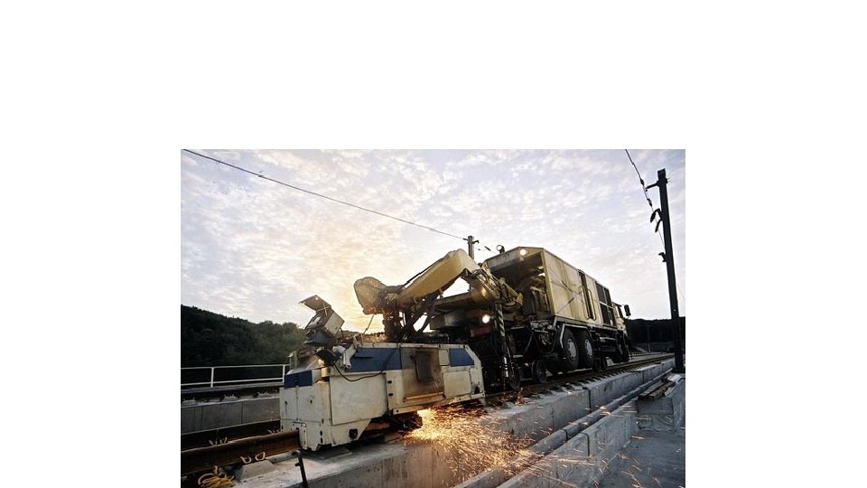
VARIOUS OPTIONS FOR FLASH BUTT WELDING • FIXED SITE DEPOTS • MOBILE FBW PLANT

BASIC COMPONENTS OF MACHINE • CLAMPING MECHANISM • FORGING MECHANISM • TRANSFORMER

SCHEMATIC REPRESENTATION OF FBW

VARIOUS OPERATIONS üRAIL STORAGE & TRANSFER üRAIL STRAIGHTENING üRAIL END CLEANING üWELDING üSTRIPPING üPOST WELD TREATMENT ü RAIL JOINT STRAIGHTENING ü RAIL HEAD PROFILING ü INSPECTION ü OUTGOING CONVEYOR SYSTEM
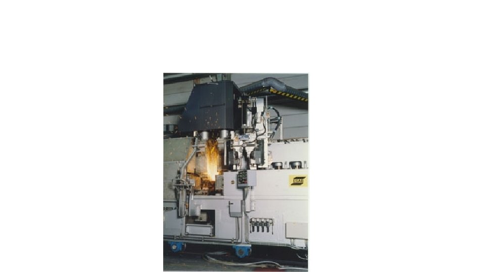

FB weld equipment

Flash butt welding

Flash-butt welding • Flash-butt welding is completely automated and is used worldwide as a welding method that provides high quality and high productivity. • A plant flash-butt welder is equipped with a transformer having a large capacity and a large hydraulic system. A mobile flash-butt welder, a miniaturized lightweight type of welder, is available.

Process • Voltage is applied across the end faces of the rails butted to each other so that an electric discharge is produced in succession through local contact, thereby heating and melting the end faces of rails. • When the faces are completed converted into a molten state, the rails are pressurized toward each other (upsetting), and both ends are pressure-welded.

Preheating process: • flash-butt welder equipped with a transformer of a large capacity, wherein the entire end faces of both the rails are short-circuited with each other, and a very high current is made to flow via electrodes. As the result thereof, the temperature increases at the weld section.

Flashing process: • Rails with a voltage applied across the end faces are made to approach each other at a programmed speed, and local electric arc discharges are repeatedly produced between the rail end faces; these discharges melt and preheat the rail end faces. Drops of molten rails are emitted outward by an electro-magnetic force

Flashing process: • When the entire end faces are completely melted, upsetting is applied. The rate of approach of the rail end faces is 0. 1 -2. 5 mm/s, and the length of the rail loss at the ends of both the rails is 10 -20 mm per rail. • In the case of mobile flash-butt welding, since there is no preheating process, the flashing time is set longer in order for the end faces to melt completely.

Recommended Butting Pressure • The recommended butting pressure for different types of rails is indicated below • 72 UTS rails – 5 kg/mm 2 on cross sectional area. • 90 UTS rails & Head Hardened rails – 6 kg/mm 2 on cross sectional areas. • 110 UTS rails – 7 kg/mm 2 on cross sectional area.

1. Pre heating, 2. flashing

3. Upsetting, 4. trimming

Upsetting process: • Rails are pressure-welded by a load applied to the end faces of the rails. Molten steel is discharged outward; the end portions near the end faces, which have been heated to a very high temperature, undergo plastic deformation, and a bulge is formed. • Pressurizing load is approximately 70 MPa, and the total pressurizing load is 500 -600 KN, Upon upsetting, the rail shrinks by 15 -25 mm.

Trimming process: • The bulge produced at the weld section is removed in the hot state by a hydraulically operated trimmer equipped with a rail-profiled blade. • Welding time: • The welding time is 1. 5 -4 min.

TESTING OF FLASH BUTT WELDS: RECORD • Record of weld Register. • Dimension check register. • USFD test Register. • Hardness test Register. • Transverse Load Test.

• Macro examination register. • Micro Examination register. • Daily Progress Register • Joint Rejection Register • Customer Complaint Register.

ULTRASONIC TESTING OF RAILS TO BE WELDED New and old but serviceable rails shall be free from internal defects. In the case of new rails, the ultrasonic testing is required to be done at the rai manufacturer’s premises. Old but serviceable rails shall invariably be tested ultrasonically before they are taken to Flash Butt Welding Plants.

RECORD OF WELDS • Record of all the joints shall be maintained in a register as per proforma. • POST WELD STRAIGHTENING • A post straightening machine shall be installed at suitable distance from the welding machine for straightening the joint if required. • WATER COOLING: • It is desirable to do post weld straightening after the weld has cooled down to ambient temperature. • Water spray cooling shall be done at such suitable distance from the welding plant where the temperature of the weld is not more than 350 degree Celsius which normally is achieved in 7 -8 rail length.

FINISHING TOLERANCES FOR WELD • Welds with new rails • Vertical misalignment : +0. 3 mm , - 0. 0 mm at the centre of a 1 m straight edge • Lateral misalignment : +0. 3 mm at the centre of a 1 m straight edge. • Head finishing (in width): Side of rail head should be finished to : • ± 0. 25 mm on gauge side at the centre of 10 cm straight edge

FISHING TOLERANCES FOR WELDS • Finishing of top table surface: + 0. 2 mm, - 0. 0 mm at the centre of 10 cm straight edge. • Web Zone ( Under side of head, +3. 0 mm of the parent contour Web, top of base, both fillet ) -0. 0 mm
 Vertical Misalignment : + 0. 5 mm at")
WELD WITH OLD RAILS • (i) Vertical Misalignment : + 0. 5 mm at the centre of a 1 m straight edge. • (ii) Lateral Misalignment : + 0. 5 mm at the centre of a 1 m straight edge. • (iii) Head finishing ( on sides) : + 0. 3 mm on the gauge side at the centre of a 10 cm straight edge. • (iv) Head finishing ( on top : +0. 2 mm on the gauge side at the centre of a table surface) 10 cm straight edge. • (v) Web zone ( under side of : + 3. 0 mm of the parent head, web, top of base and -0. 0 mm contour both fillets )

STRENGTH YIELD STRENGTH S. N o TYPE OF RAIL 1 72 UTS 2 90 UTS YIELD UTS STRENGTH (MPA) RAIL WELD 441 445 755 716 539 559 978 779

FATIGUE STRENGTH S. No. DESCRIPTION FATIGUE STRENGTH 1 RAIL 28 Kg/mm 2 2 52 Kg 72 UTS 28 Kg/mm 2

IMPACT STRENGTH RAIL SECTION 52 Kg 72 UTS IMPACT STRENGTH OF WELD AS % OF PARENT RAIL 10 52 Kg 90 UTS 7. 37 60 Kg 90 UTS 7. 14

Planning & Executing TWR with mobile FBW plant including tender schedule, specifications & conditions
 • In")
Mobile flash butt welding plants ( Bds letter no. 2017/w-1/genl/policy dated 18/02/2017) • In situ mobile flash butt welding of rail is permitted with following safe guards: • QAP duly approved by RDSO. • QAP for every site be prepared and approved by ce/con in consultation with CTE of the railway. • Adequate training to workers & supervisors of contractors/departmental be ensured by Dyce/con. • 10% test check by Dyce/con

Team for mobile FB plant • One supervisor and two welders. • Educational qualification of supervisor be diploma in mech/elec or Bsc • Educational qualification of welder is class X or equivalent passed • Competency to welders be given only after written and interview followed by practical test.

Periodical inspection of mobile FB plants • Inspected by OEM or his authorized representative at an interval of two years or execution of 20000 joints which earlier to conduct technical audit of its health.

QAP for mobile FB Plants. ( As per annexure –X Para 5. 6. 2 ) Cslip no. 2 to mannual for FB welding of rails. • Submission of General Quality Assurance Programme. By agency to RDSO. Availability of Railways order not Required. • Approval of Welding Team: once contract is awarded CTE of Zonal Railway will issue Competency Certificate. • Submission of Final QAP: after approval of welding team by Zonal Railway, firm do internal test to fix the welding Parameters for Rails of different section. Then submit to RDSO for standardisation of weld Parameter. RDSO will Approve.

Field approval of welding. • Procedure approval shall be carried out by RDSO as per Para 5. 6 of manual. • After procedure approval field welding for mobile flush butt weld plant is permitted. After 30 welds on track if CTE/CE(C) and Engineer in-charge satisfy as per weld acceptance criteria defined in Para 5. 6 permitted for regular welding in field.

FBW S. MUTHALAGAN INSTRUCTOR SRCETC/TBM 46

FBW S. MUTHALAGAN INSTRUCTOR SRCETC/TBM 47

Tender schedule, specifications & conditions

Tender Schedule, Specifications & Conditions

Tender schedule, specifications & conditions

Tender schedule, specifications & conditions

Tender schedule, specifications & conditions

Tender schedule, specifications & conditions

Tender schedule, specifications & conditions

Tender schedule, specifications & conditions
- Slides: 55