
Part 2 1 Summary Dynamical Operation Vector Control
- Slides: 51
Part 2 - 1 Summary Dynamical Operation, Vector Control, DTC and Encoder-less Operation ©Copyright Ned Mohan 2005, by permission from MNPERE
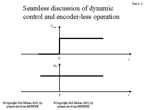
Seamless discussion of dynamic control and encoder-less operation ©Copyright Ned Mohan 2005, by permission from MNPERE Part 2 - 2
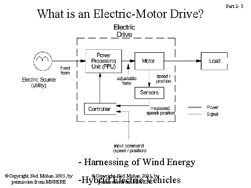
What is an Electric-Motor Drive? - Harnessing of Wind Energy ©Copyright Ned Mohan 2005, by permission from MNPERE ©Copyright Ned Mohan 2005, by -Hybrid Electric Vehicles permission from MNPERE Part 2 - 3
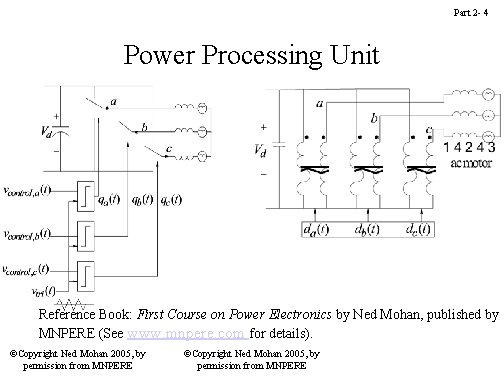
Part 2 - 4 Power Processing Unit Reference Book: First Course on Power Electronics by Ned Mohan, published by MNPERE (See www. mnpere. com for details). ©Copyright Ned Mohan 2005, by permission from MNPERE
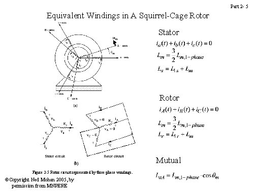
Part 2 - 5 Equivalent Windings in A Squirrel-Cage Rotor Stator Rotor (b) Figure 2 -5 Rotor circuit represented by three-phase windings. ©Copyright Ned Mohan 2005, by permission from MNPERE Mutual
Part 2 - 6 Dynamic Analysis of Induction Machines in Terms of dq-Windings ©Copyright Ned Mohan 2005, by permission from MNPERE
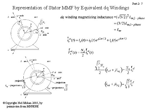
Representation of Stator MMF by Equivalent dq Windings ©Copyright Ned Mohan 2005, by permission from MNPERE Part 2 - 7
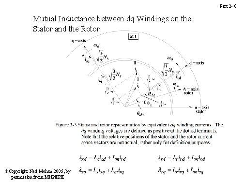
Part 2 - 8 Mutual Inductance between dq Windings on the Stator and the Rotor ©Copyright Ned Mohan 2005, by permission from MNPERE
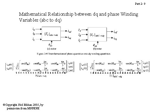
Part 2 - 9 Mathematical Relationship between dq and phase Winding Variables (abc to dq) ©Copyright Ned Mohan 2005, by permission from MNPERE
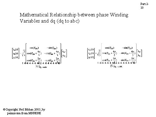
Part 210 Mathematical Relationship between phase Winding Variables and dq (dq to abc) ©Copyright Ned Mohan 2005, by permission from MNPERE
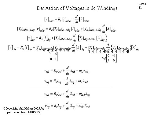
Derivation of Voltages in dq Windings ©Copyright Ned Mohan 2005, by permission from MNPERE Part 211
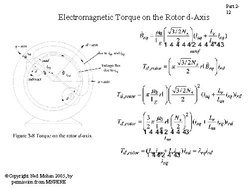
Electromagnetic Torque on the Rotor d-Axis ©Copyright Ned Mohan 2005, by permission from MNPERE Part 212
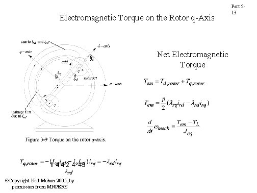
Electromagnetic Torque on the Rotor q-Axis Net Electromagnetic Torque ©Copyright Ned Mohan 2005, by permission from MNPERE Part 213
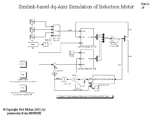
Simlink-based dq-Axis Simulation of Induction Motor ©Copyright Ned Mohan 2005, by permission from MNPERE Part 214
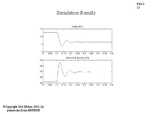
Part 215 Simulation Results ©Copyright Ned Mohan 2005, by permission from MNPERE
Part 216 Mathematical Description of Vector Control ©Copyright Ned Mohan 2005, by permission from MNPERE
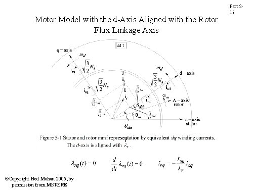
Motor Model with the d-Axis Aligned with the Rotor Flux Linkage Axis ©Copyright Ned Mohan 2005, by permission from MNPERE Part 217
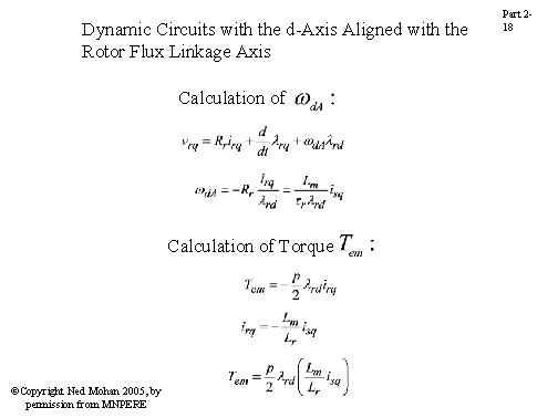
Dynamic Circuits with the d-Axis Aligned with the Rotor Flux Linkage Axis Calculation of Torque ©Copyright Ned Mohan 2005, by permission from MNPERE Part 218
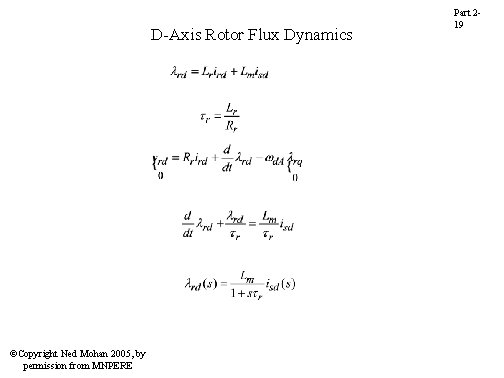
D-Axis Rotor Flux Dynamics ©Copyright Ned Mohan 2005, by permission from MNPERE Part 219
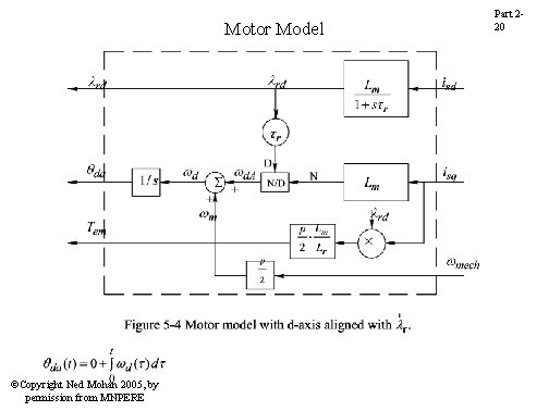
Motor Model ©Copyright Ned Mohan 2005, by permission from MNPERE Part 220
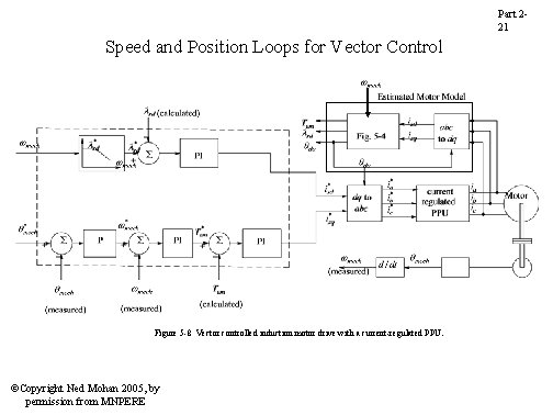
Part 221 Speed and Position Loops for Vector Control Figure 5 -8 Vector controlled induction motor drive with a current-regulated PPU. ©Copyright Ned Mohan 2005, by permission from MNPERE
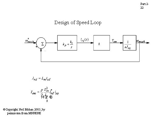
Part 222 Design of Speed Loop ©Copyright Ned Mohan 2005, by permission from MNPERE
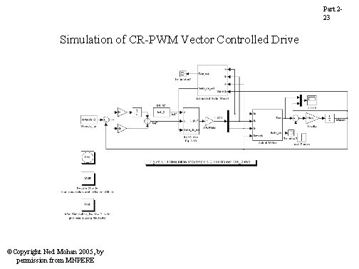
Part 223 Simulation of CR-PWM Vector Controlled Drive using Simulink ©Copyright Ned Mohan 2005, by permission from MNPERE
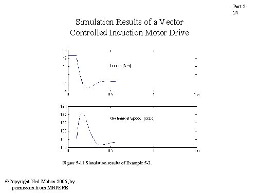
Part 224 Simulation Results of a Vector Controlled Induction Motor Drive ©Copyright Ned Mohan 2005, by permission from MNPERE
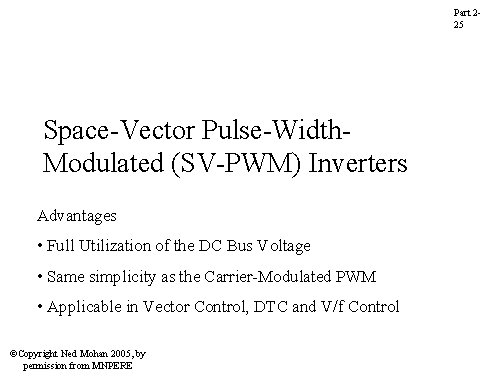
Part 225 Space-Vector Pulse-Width. Modulated (SV-PWM) Inverters Advantages • Full Utilization of the DC Bus Voltage • Same simplicity as the Carrier-Modulated PWM • Applicable in Vector Control, DTC and V/f Control ©Copyright Ned Mohan 2005, by permission from MNPERE
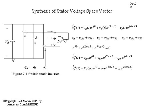
Synthesis of Stator Voltage Space Vector ©Copyright Ned Mohan 2005, by permission from MNPERE Part 226
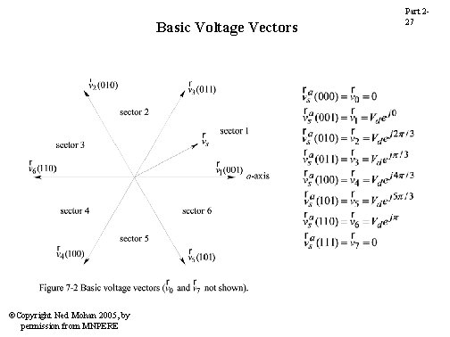
Basic Voltage Vectors ©Copyright Ned Mohan 2005, by permission from MNPERE Part 227
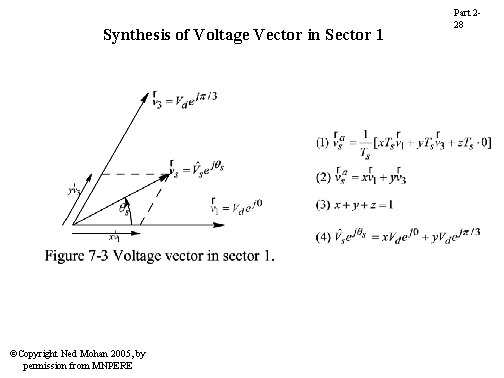
Synthesis of Voltage Vector in Sector 1 ©Copyright Ned Mohan 2005, by permission from MNPERE Part 228
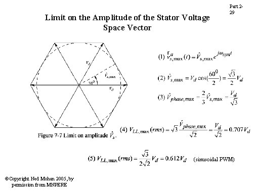
Limit on the Amplitude of the Stator Voltage Space Vector Part 229 (sinusoidal PWM) ©Copyright Ned Mohan 2005, by permission from MNPERE
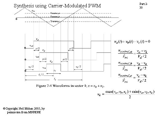
Synthesis using Carrier-Modulated PWM ©Copyright Ned Mohan 2005, by permission from MNPERE Part 230
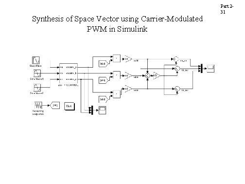
Synthesis of Space Vector using Carrier-Modulated PWM in Simulink ©Copyright Ned Mohan 2005, by permission from MNPERE Part 231
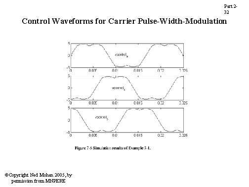
Part 232 Control Waveforms for Carrier Pulse-Width-Modulation ©Copyright Ned Mohan 2005, by permission from MNPERE
Part 233 Direct Torque Control (DTC) and Encoder-less Operation of Induction Motors ©Copyright Ned Mohan 2005, by permission from MNPERE
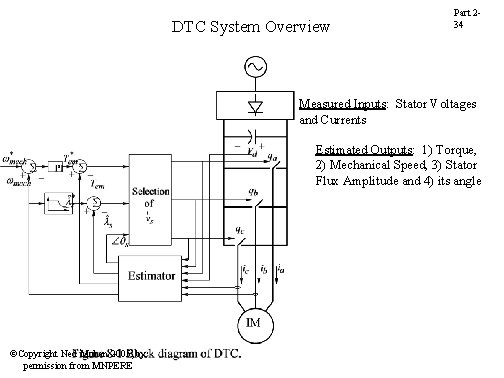
DTC System Overview Part 234 Measured Inputs: Stator Voltages and Currents Estimated Outputs: 1) Torque, 2) Mechanical Speed, 3) Stator Flux Amplitude and 4) its angle ©Copyright Ned Mohan 2005, by permission from MNPERE
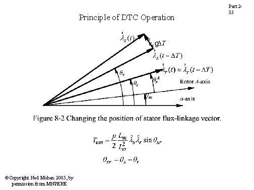
Principle of DTC Operation ©Copyright Ned Mohan 2005, by permission from MNPERE Part 235
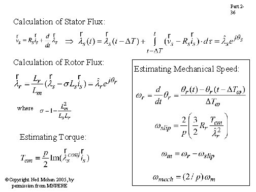
Part 236 Calculation of Stator Flux: Calculation of Rotor Flux: where Estimating Torque: ©Copyright Ned Mohan 2005, by permission from MNPERE Estimating Mechanical Speed:
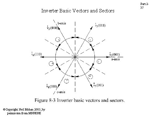
Inverter Basic Vectors and Sectors ©Copyright Ned Mohan 2005, by permission from MNPERE Part 237
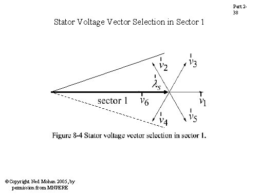
Part 238 Stator Voltage Vector Selection in Sector 1 ©Copyright Ned Mohan 2005, by permission from MNPERE
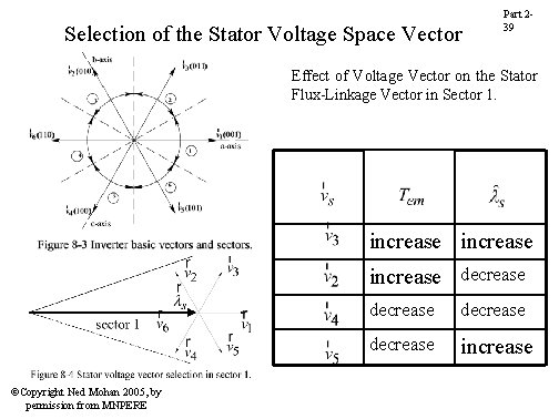
Selection of the Stator Voltage Space Vector Part 239 Effect of Voltage Vector on the Stator Flux-Linkage Vector in Sector 1. increase decrease ©Copyright Ned Mohan 2005, by permission from MNPERE decrease increase
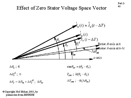
Effect of Zero Stator Voltage Space Vector ©Copyright Ned Mohan 2005, by permission from MNPERE Part 240
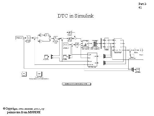
Part 241 DTC in Simulink ©Copyright Ned Mohan 2005, by permission from MNPERE
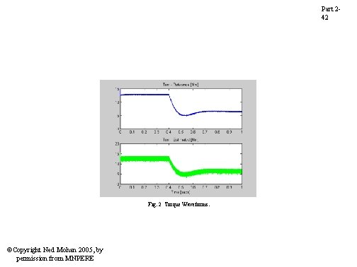
Part 242 Fig. 2 Torque Waveforms. ©Copyright Ned Mohan 2005, by permission from MNPERE
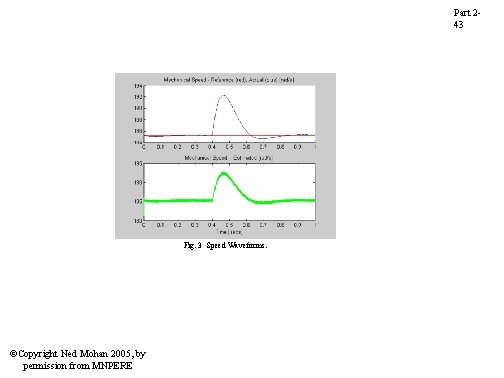
Part 243 Fig. 3 Speed Waveforms. ©Copyright Ned Mohan 2005, by permission from MNPERE
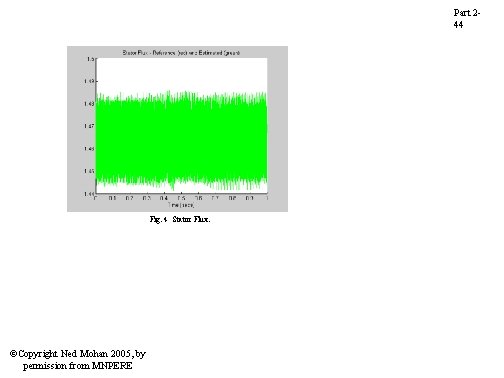
Part 244 Fig. 4 Stator Flux. ©Copyright Ned Mohan 2005, by permission from MNPERE
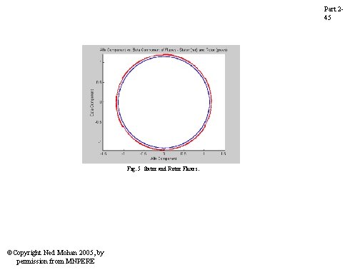
Part 245 Fig. 5 Stator and Rotor Fluxes. ©Copyright Ned Mohan 2005, by permission from MNPERE
Part 246 Vector Control of Permanent. Magnet Synchronous-Motor Drives ©Copyright Ned Mohan 2005, by permission from MNPERE
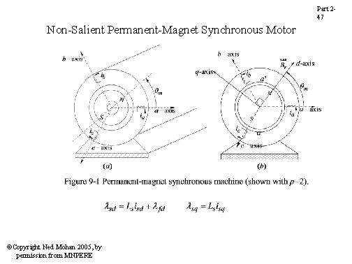
Part 247 Non-Salient Permanent-Magnet Synchronous Motor ©Copyright Ned Mohan 2005, by permission from MNPERE
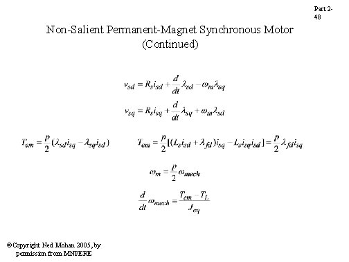
Part 248 Non-Salient Permanent-Magnet Synchronous Motor (Continued) ©Copyright Ned Mohan 2005, by permission from MNPERE
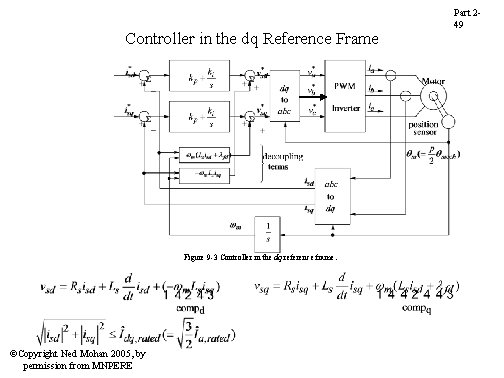
Controller in the dq Reference Frame Figure 9 -3 Controller in the dq reference frame. ©Copyright Ned Mohan 2005, by permission from MNPERE Part 249
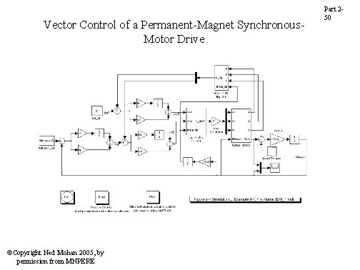
Vector Control of a Permanent-Magnet Synchronous. Motor Drive ©Copyright Ned Mohan 2005, by permission from MNPERE Part 250
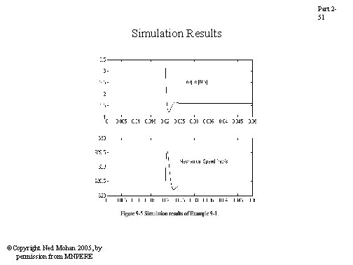
Part 251 Simulation Results ©Copyright Ned Mohan 2005, by permission from MNPERE