
Parkinson SAT CDR Bruninga USN ret David Koeppel
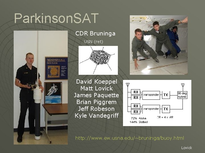
Parkinson. SAT CDR Bruninga USN (ret) David Koeppel Matt Lovick James Paquette Brian Piggrem Jeff Robeson Kyle Vandegriff http: //www. ew. usna. edu/~bruninga/buoy. html Lovick
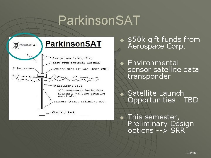
Parkinson. SAT u u $50 k gift funds from Aerospace Corp. Environmental sensor satellite data transponder Satellite Launch Opportunities - TBD This semester, Preliminary Design options --> SRR Lovick
Proposed Mission u u u Relay data from simple environmental sensors – buoys – in the Chesapeake Bay or oceans or onshore. Providing position/ status and telemetry about 2 to 4 times a day to the Internet. Including Buoys elsewhere around the world as long as Internet linked ground stations are in the footprint. Establish this channel/system as a global resource for other such experiments in the Amateur Satellite Service. Inspire other schools and universities to participate with additional low cost satellite transponders and buoy and sensor systems. Serve as a technology demonstrator for various spacecraft subsystems including basic attitude control, follow-ons to PCSAT experiments and other student projects such as the MIDN sensor. Support an Ocean Data Telemetry Microsat Link (ODTML) UHF transponder for DOD and maybe UHF RFI Mitigation Lovick
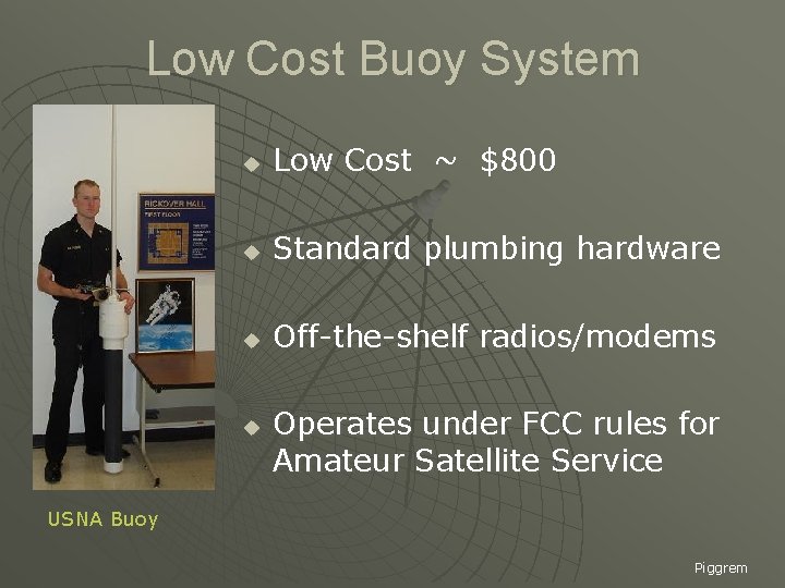
Low Cost Buoy System u Low Cost ~ $800 u Standard plumbing hardware u Off-the-shelf radios/modems u Operates under FCC rules for Amateur Satellite Service USNA Buoy Piggrem
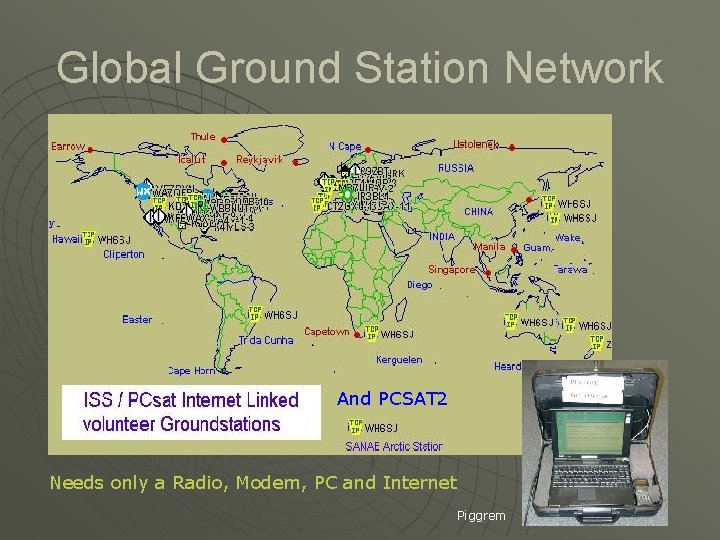
Global Ground Station Network And PCSAT 2 Needs only a Radio, Modem, PC and Internet Piggrem
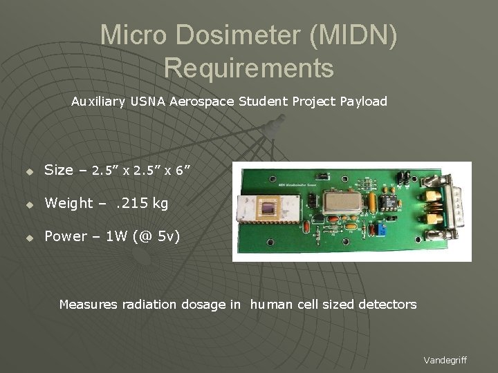
Micro Dosimeter (MIDN) Requirements Auxiliary USNA Aerospace Student Project Payload u Size – 2. 5” x 6” u Weight – . 215 kg u Power – 1 W (@ 5 v) Measures radiation dosage in human cell sized detectors Vandegriff
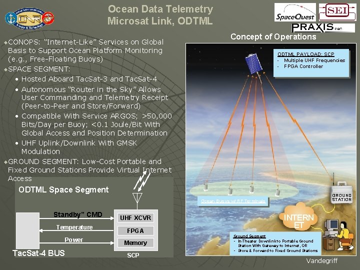
Ocean Data Telemetry Microsat Link, ODTML u. CONOPS: “Internet-Like” Services on Global Concept of Operations Basis to Support Ocean Platform Monitoring (e. g. , Free-Floating Buoys) u. SPACE SEGMENT: • Hosted Aboard Tac. Sat-3 and Tac. Sat-4 • Autonomous “Router in the Sky” Allows User Commanding and Telemetry Receipt (Peer-to-Peer and Store/Forward) • Compatible With Service ARGOS; >50, 000 Bits/Day per Buoy; <0. 1 Joule/Bit With Global Access and Position Determination • UHF Uplink/Downlink With GMSK Modulation u. GROUND SEGMENT: Low-Cost Portable and Fixed Ground Stations Provide Virtual Internet Access ODTML PAYLOAD: SCP - Multiple UHF Frequencies - FPGA Controller ODTML Space Segment GROUND STATION Ocean Buoys w/ RF Terminals Standby” CMD Temperature Power Tac. Sat-4 BUS UHF XCVR FPGA Memory SCP INTERN ET Ground Segment • In-Theater Downlink to Portable Ground Station With Gateway to Internet, OR • Store & Forward to Fixed Ground Stations USE R Vandegriff
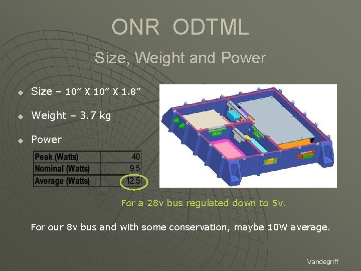
ONR ODTML Size, Weight and Power u Size – 10” X 1. 8” u Weight – 3. 7 kg u Power For a 28 v bus regulated down to 5 v. For our 8 v bus and with some conservation, maybe 10 W average. Vandegriff
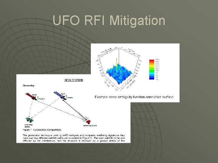
UFO RFI Mitigation
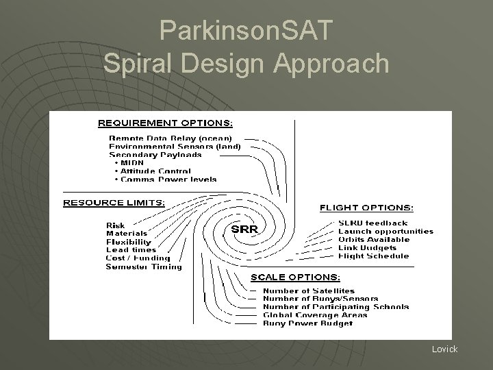
Parkinson. SAT Spiral Design Approach Lovick
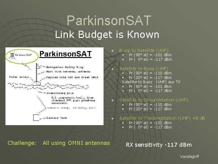
Parkinson. SAT Link Budget is Known u Buoy to Satellite (VHF) • • u Pr (90° el) = -101 d. Bm Pr ( 0° el) = -117 d. Bm Satellite to Buoy (UHF) • Pr (90° el) = -110 d. Bm • Pr (20° el) = -117 d. Bm Satellite to Buoy (VHF) aux TX • Pr (90° el) = -101 d. Bm • Pr ( 0° el) = -117 d. Bm u Satellite to Groundstation (UHF) • • u Satellite to Trackingstation (UHF) +8 d. B • • Challenge: All using OMNI antennas Pr (90° el) = -110 d. Bm Pr (20° el) = -117 d. Bm Pr (90° el) = -102 d. Bm Pr ( 0° el) = -117 d. Bm RX sensitivity -117 d. Bm Vandegriff
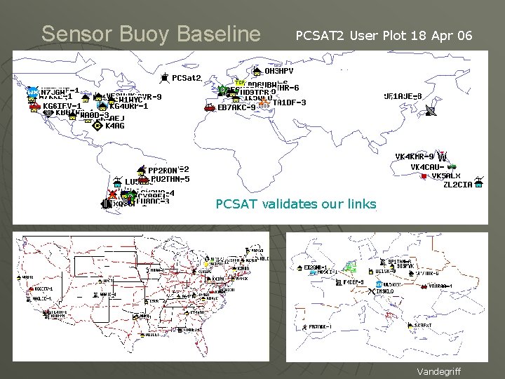
Sensor Buoy Baseline PCSAT 2 User Plot 18 Apr 06 PCSAT validates our links Vandegriff
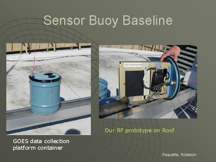
Sensor Buoy Baseline Our RF prototype on Roof GOES data collection platform container Paquette, Robeson
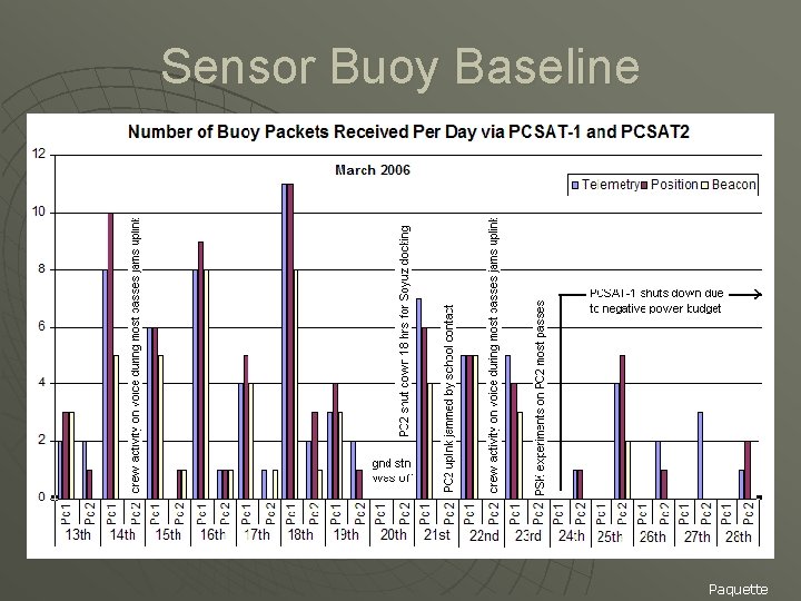
Sensor Buoy Baseline Paquette
Launch Opportunities u Free Flyer (comms orbit) - Desired u Attached Payload – OK u Space Shuttle – too low, no life… • Available Launcher – 5” picosat (minimum system) • Requires a Propulsion system (H 2 O 2 man-safe) Robeson
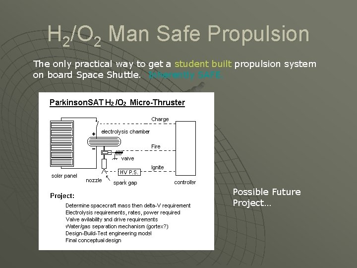
H 2/O 2 Man Safe Propulsion The only practical way to get a student built propulsion system on board Space Shuttle. Inherently SAFE. Possible Future Project…
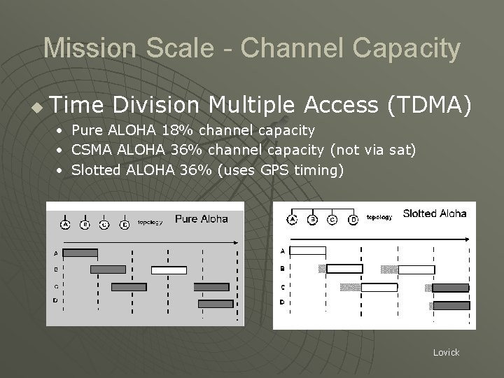
Mission Scale - Channel Capacity u Time Division Multiple Access (TDMA) • Pure ALOHA 18% channel capacity • CSMA ALOHA 36% channel capacity (not via sat) • Slotted ALOHA 36% (uses GPS timing) Lovick
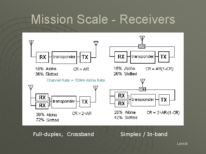
Mission Scale - Receivers Channel Rate = TDMA Aloha Rate Full-duplex, Crossband Simplex / In-band Lovick
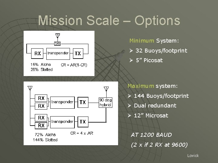
Mission Scale – Options Minimum System: Ø 32 Buoys/footprint Ø 5” Picosat Maximum system: Ø 144 Buoys/footprint Ø Dual redundant Ø 12” Microsat AT 1200 BAUD (2 x if 2 RX at 9600) Lovick
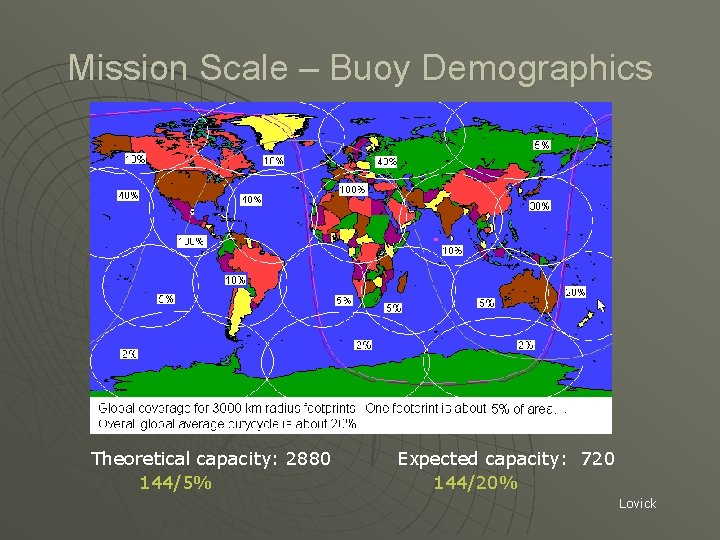
Mission Scale – Buoy Demographics Theoretical capacity: 2880 144/5% Expected capacity: 720 144/20% Lovick
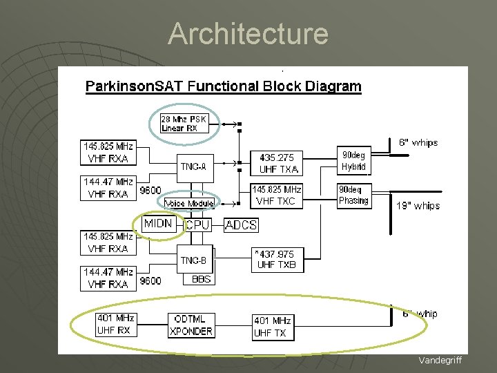
Architecture Vandegriff
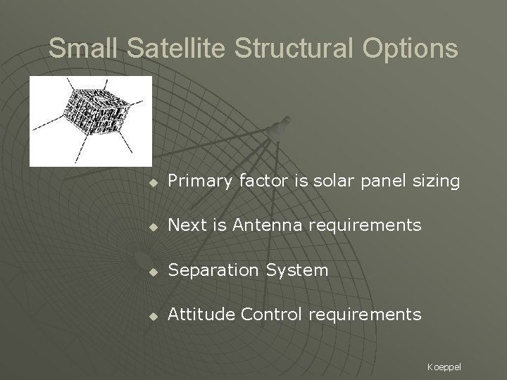
Small Satellite Structural Options u Primary factor is solar panel sizing u Next is Antenna requirements u Separation System u Attitude Control requirements Koeppel
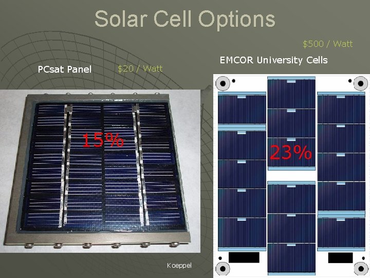
Solar Cell Options $500 / Watt PCsat Panel EMCOR University Cells $20 / Watt 15% 23% Koeppel
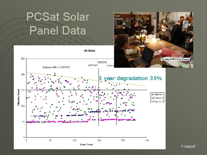
PCSat Solar Panel Data 5 year degradation 35% Koeppel
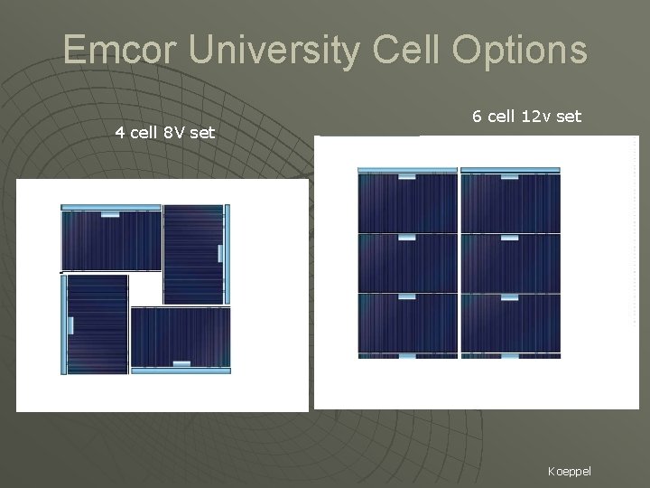
Emcor University Cell Options 4 cell 8 V set 6 cell 12 v set Koeppel
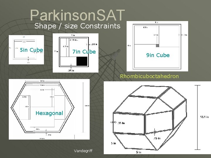
Parkinson. SAT Shape / size Constraints 5 in Cube 7 in Cube 9 in Cube Rhombicuboctahedron Hexagonal Vandegriff
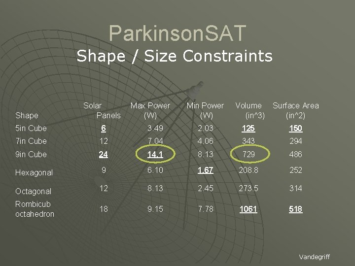
Parkinson. SAT Shape / Size Constraints Shape Solar Panels Max Power (W) Min Power (W) Volume Surface Area (in^3) (in^2) 5 in Cube 6 3. 49 2. 03 125 150 7 in Cube 12 7. 04 4. 06 343 294 9 in Cube 24 14. 1 8. 13 729 486 Hexagonal 9 6. 10 1. 67 208. 8 252 Octagonal 12 8. 13 2. 45 273. 5 314 Rombicub octahedron 18 9. 15 7. 78 1061 518 Vandegriff
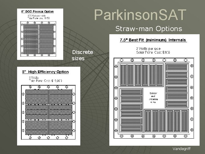
Parkinson. SAT Straw-man Options Discrete sizes Vandegriff
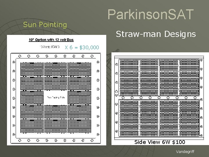
Sun Pointing Parkinson. SAT Straw-man Designs X 6 = $30, 000 Side View 6 W $100 Vandegriff
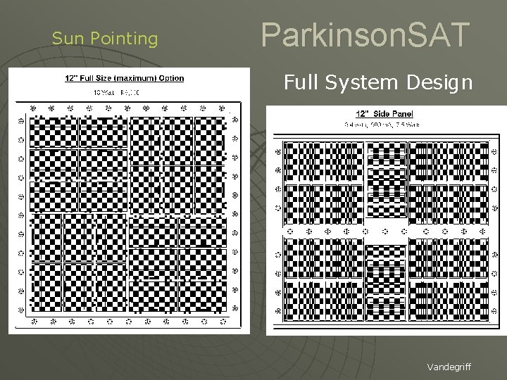
Sun Pointing Parkinson. SAT Full System Design Vandegriff
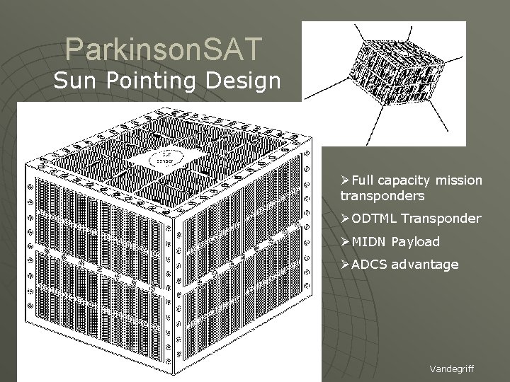
Parkinson. SAT Sun Pointing Design ØFull capacity mission transponders ØODTML Transponder ØMIDN Payload ØADCS advantage Vandegriff
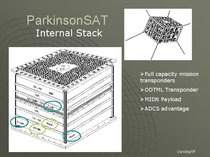
Parkinson. SAT Internal Stack ØFull capacity mission transponders ØODTML Transponder ØMIDN Payload ØADCS advantage Vandegriff
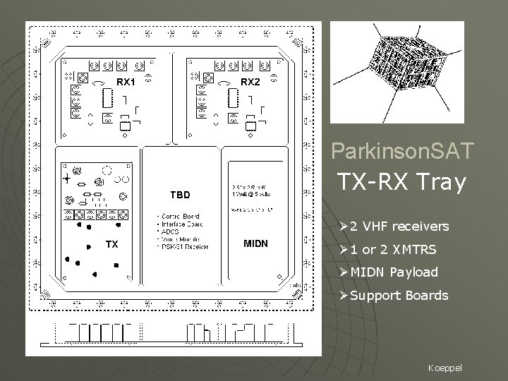
Parkinson. SAT TX-RX Tray Ø 2 VHF receivers Ø 1 or 2 XMTRS ØMIDN Payload ØSupport Boards Koeppel
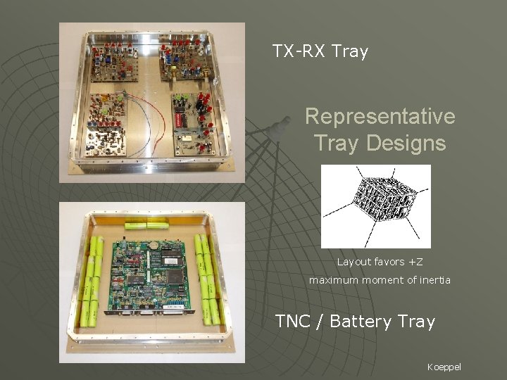
TX-RX Tray Representative Tray Designs Layout favors +Z maximum moment of inertia TNC / Battery Tray Koeppel
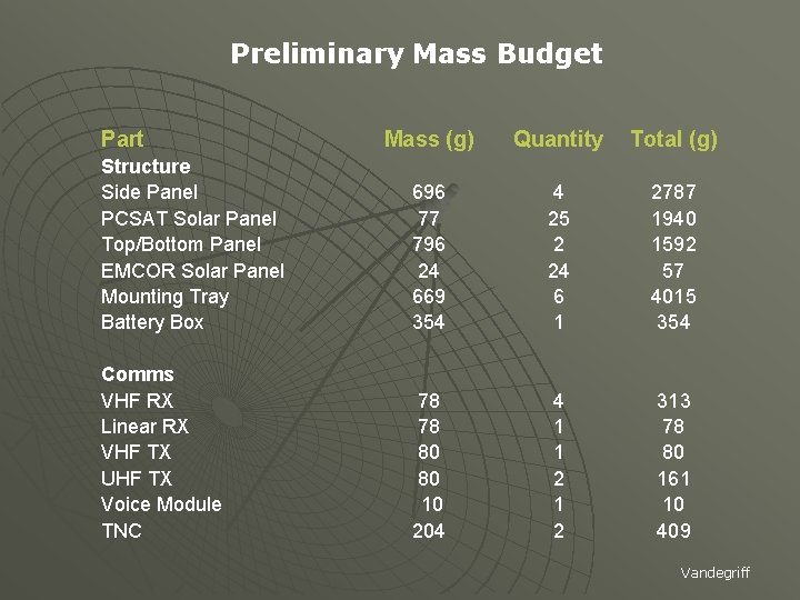
Preliminary Mass Budget Part Mass (g) Quantity Total (g) Structure Side Panel PCSAT Solar Panel Top/Bottom Panel EMCOR Solar Panel Mounting Tray Battery Box 696 77 796 24 669 354 4 25 2 24 6 1 2787 1940 1592 57 4015 354 Comms VHF RX Linear RX VHF TX UHF TX Voice Module TNC 78 78 80 80 10 204 4 1 1 2 313 78 80 161 10 409 Vandegriff
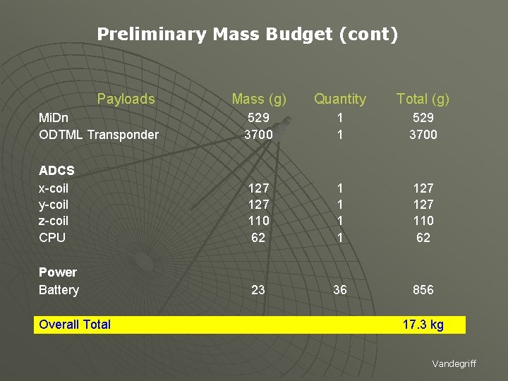
Preliminary Mass Budget (cont) Payloads Mass (g) Quantity Total (g) Mi. Dn ODTML Transponder 529 3700 1 1 529 3700 ADCS x-coil y-coil z-coil CPU 127 110 62 1 1 127 110 62 Power Battery 23 36 856 17. 3 kg Overall Total Vandegriff
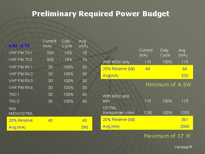
Preliminary Required Power Budget 4 RX / 2 TX Current (m. A) Duty Cycle Avg (m. A) VHF FM TX 1 500 15% 75 VHF FM TX 2 500 15% 75 VHF FM RX 1 30 100% VHF FM RX 2 30 VHF FM RX 3 Current (m. A) Duty Cycle Avg (m. A) With Mi. Dn only 119 100% 119 30 20% Reserve (tot) 64 64 100% 30 Avg(m. A) 533 30 100% 30 VHF FM RX 4 30 100% 30 TNC 1 30 100% 40 TNC 2 30 100% 40 W/o Mi. Dn/ODTML 20% Reserve Avg (m. A) Minimum of 4. 5 W With Mi. Dn and with 119 100% 119 ODTML transponder (10 W) 1200 100% 1200 40 40 20% Reserve (tot) 361 390 Avg (m. A) 2040 Maximum of 17 W Vandegriff
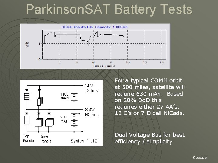
Parkinson. SAT Battery Tests For a typical COMM orbit at 500 miles, satellite will require 630 m. Ah. Based on 20% Do. D this requires either 27 AA’s, 12 C’s or 7 D cell Ni. Cads. Dual Voltage Bus for best efficiency / simplicity Koeppel
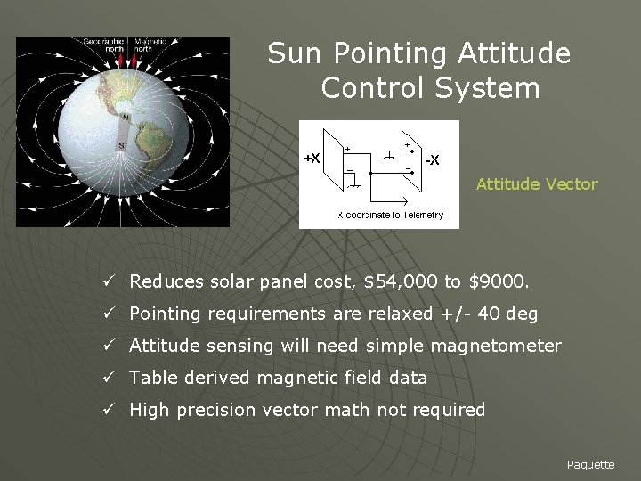
Sun Pointing Attitude Control System Attitude Vector ü Reduces solar panel cost, $54, 000 to $9000. ü Pointing requirements are relaxed +/- 40 deg ü Attitude sensing will need simple magnetometer ü Table derived magnetic field data ü High precision vector math not required Paquette
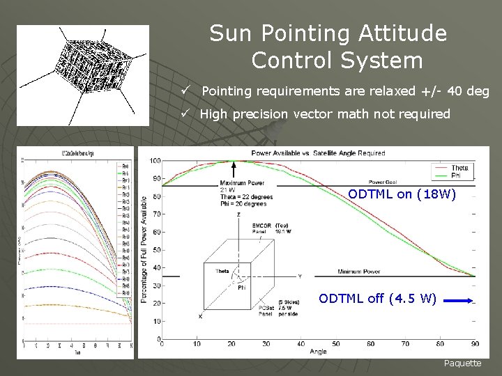
Sun Pointing Attitude Control System ü Pointing requirements are relaxed +/- 40 deg ü High precision vector math not required ODTML on (18 W) ODTML off (4. 5 W) Paquette
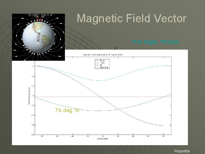
Magnetic Field Vector Prof Ingle, Physics 76 deg W Paquette

Magnetic Field Vector Prof Ingle, Physics Paquette
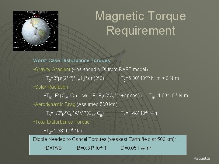
Magnetic Torque Requirement Worst Case Disturbance Torques: • Gravity Gradient (~balanced MOI from RAFT model) • Tg=3*μ/(2*r 3)*|Iz-Iy|*sin(2*θ) Tg=6. 30*10 -25 N-m ≈ 0 N-m • Solar Radiation • Tsp=F*(Cps-Cg) w/ F=Fs/C*As*(1+q)*cos(i) Tsp=1. 03*10 -7 N-m • Aerodynamic Drag (Assumed 500 km) • Ta=1/2*ρ*CD*A*V 2*(Cpa-Cg) Ta=1. 48*10 -6 N-m • Total Disturbance Torque • Td=1. 58*10 -6 N-m Dipole Needed to Cancel Torques (weakest Earth field at 500 km): • D=Td/B B=0. 31*10 -4 T D=0. 051 A-m 2 Paquette
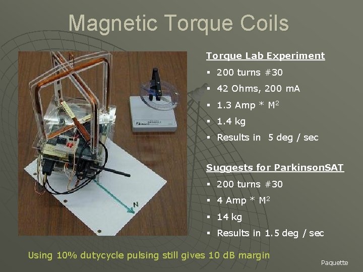
Magnetic Torque Coils Torque Lab Experiment § 200 turns #30 § 42 Ohms, 200 m. A § 1. 3 Amp * M 2 § 1. 4 kg § Results in 5 deg / sec Suggests for Parkinson. SAT § 200 turns #30 § 4 Amp * M 2 § 14 kg § Results in 1. 5 deg / sec Using 10% dutycycle pulsing still gives 10 d. B margin Paquette
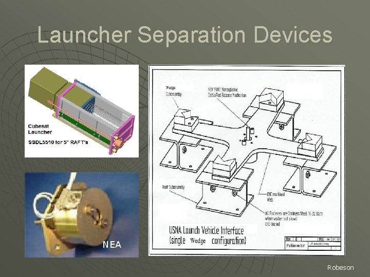
Launcher Separation Devices NEA Robeson
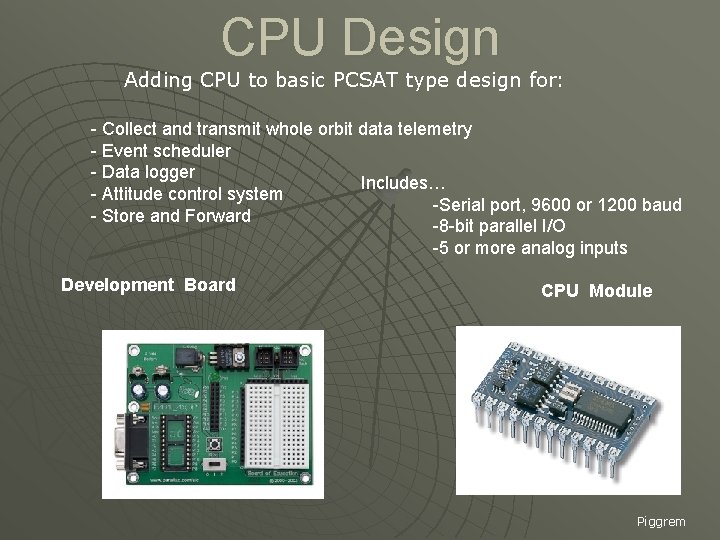
CPU Design Adding CPU to basic PCSAT type design for: - Collect and transmit whole orbit data telemetry - Event scheduler - Data logger Includes… - Attitude control system -Serial port, 9600 or 1200 baud - Store and Forward -8 -bit parallel I/O -5 or more analog inputs Development Board CPU Module Piggrem
Prototype Buoy Design u Design aspects similar to spacecraft: • Power System (EPS) (low-power & efficiency) • Communications System (link budget) • Sensor system (collaborating with Oceanography) • Telemetry System • Antenna System (antenna patterns) u Structure • Collaborating with Hydro Lab Piggrem
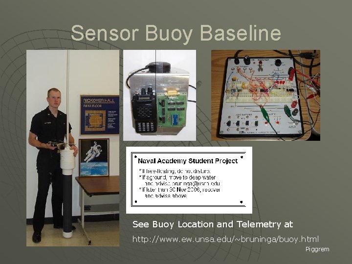
Sensor Buoy Baseline See Buoy Location and Telemetry at http: //www. ew. unsa. edu/~bruninga/buoy. html Piggrem
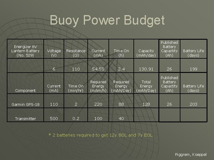
Buoy Power Budget Energizer 6 V Lantern Battery (No. 529) Voltage (V) Resistance (Ω) Current (m. A) Time On (h) Capacity (m. Ah/day) Published Battery Capactity (Ah) 6 110 54. 55 2. 4 130. 91 26 199 Battery Life (days) Component Current (m. A) Time On (min/hr) Required Energy (m. Am/h) Required Energy (m. Ah/Day) Total Energy (m. Ah/Day) Published Battery Capactity (Ah) Garmin GPS-18 110 2 220 88 128 26 203 Transmitter 500 0. 2 100 40 * 2 batteries required to get 12 v BOL and 7 v EOL Piggrem, Koeppel
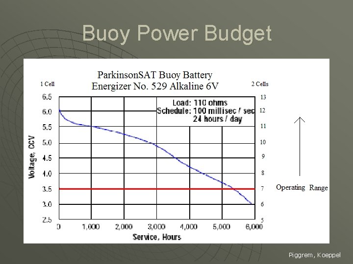
Buoy Power Budget Piggrem, Koeppel
Buoy Logic Timing Design Prescribed Timing Requirements for Bay Mission • GPS – 1. 4 minutes on every 23. 4 minutes • Transmits every 10 minutes • TNC – 11 seconds on every 11 minutes Prescribed Timing Requirements for Ocean Mission • TNC – 22 seconds on every 2. 9 minutes • GPS – 1. 4 minutes every 46. 9 minutes • Transmits every 2. 9 minutes Lovick
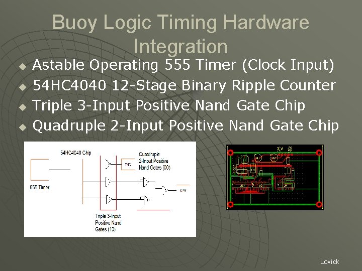
Buoy Logic Timing Hardware Integration u u Astable Operating 555 Timer (Clock Input) 54 HC 4040 12 -Stage Binary Ripple Counter Triple 3 -Input Positive Nand Gate Chip Quadruple 2 -Input Positive Nand Gate Chip Lovick
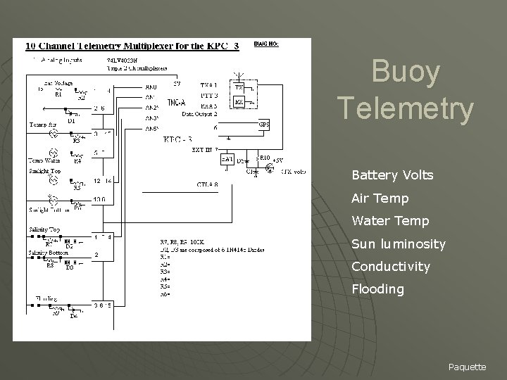
Buoy Telemetry Battery Volts Air Temp Water Temp Sun luminosity Conductivity Flooding Paquette
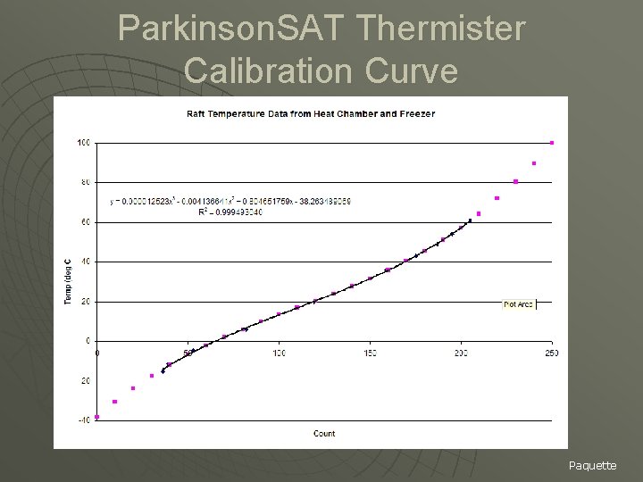
Parkinson. SAT Thermister Calibration Curve Paquette
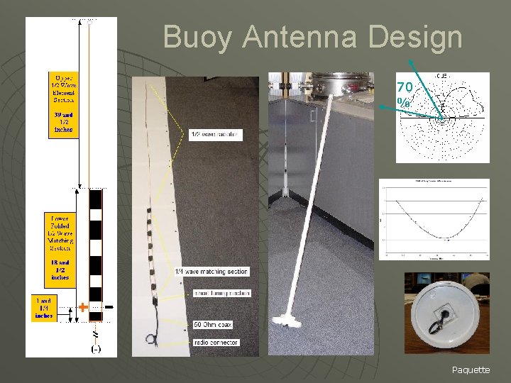
Buoy Antenna Design 70 % Paquette
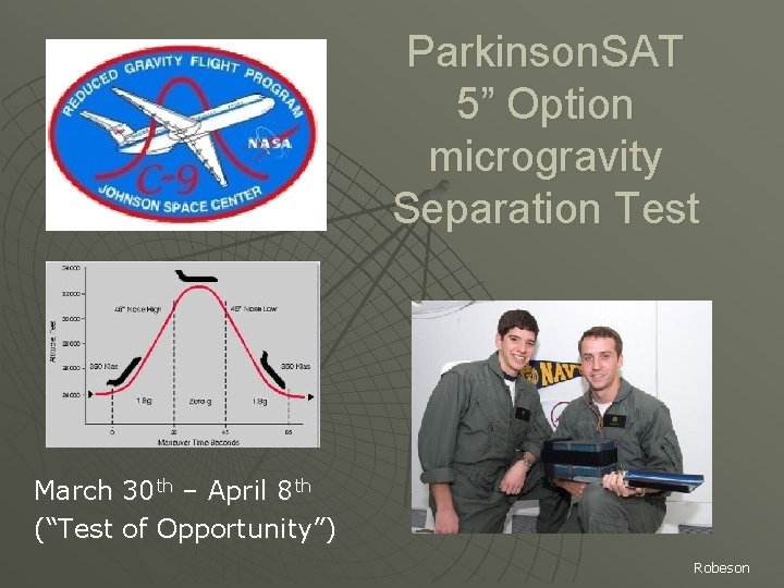
Parkinson. SAT 5” Option microgravity Separation Test March 30 th – April 8 th (“Test of Opportunity”) Robeson
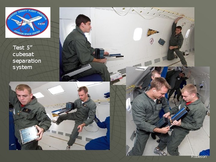
Test 5” cubesat separation system Robeson
Questions?
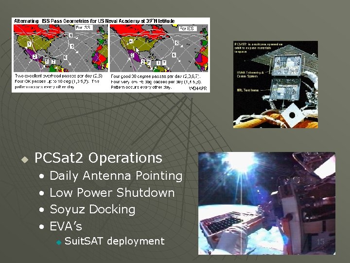
u PCSat 2 Operations • • Daily Antenna Pointing Low Power Shutdown Soyuz Docking EVA’s u Suit. SAT deployment
- Slides: 60