Packaging of RMD APDs with External Mesh Electrodes


- Slides: 10

Packaging of RMD APDs with External Mesh Electrodes on U-Penn Amplifiers Bert Harrop Princeton University Mar. 17, 2017

RMD 8 x 8 mm 2 APD – Al-mesh-screen scenario (Nov. 15, 2012) http: //physics. princeton. edu/~mcdonald/LHC/Tsang/APD_8 x 8 mm_mesh_screen_111512 k. ppt Sketch by Thomas Tsang Output to Scope - HV connected to “top” (p-side) Ground p+ n+ APD Mesh Screen (“top” side) Kapton Tape, 0. 002 in. n-side contact on original APD Sintered Au layer (“bottom” side) Al 2 O 3 Substrate Contact between screen and n+ side made by Au epoxy thru hole in Kapton Mc. Master 9227 T 417, 200 mesh, 33. 6% open Al mesh screen connection spacing ~ 128 µm opening ~ 85 µm 2 -mil Kapton (Kapton transmit > 93% 980 nm light)

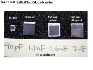
2017: Magnetron Sputtering of Top/Bottom APD Contacts A bare RMD APD die is 10 x 10 mm 2. The sensitive area is about 8 x 8 mm 2. The top (p-side) is photosensitive. A small electrical contact is made to the top side. The bottom (n-side) has a 7 x 7 mm 2 “mesa, ” which serves as a large electrical contact. Bottom Contact (Mesa) These contacts are made by sputtering Ti/Au layers of 20/200 nm. Top Contact (Dot)

Applying the conductive H 22 E Epotek Silver Epoxy to the 10 x 10 mm 2 Contact Pad of the Penn PCB Apply Thin Film (50 m) Adhesive Create 7 x 7 mm 2 opening in Mask Apply Silver Epoxy, Remove Mask

Die Bonding of the APD Placing APD onto epoxy Cure Epoxy in Vacuum Oven 5 Minutes @ 150 C

Wire Bond Top Contact (for –HV) 25 - m-Al Wirebond (Wedge)

Electroplated Ni Mesh 5 - m sheet of 100 electroplated Ni meshes (Au flashed). 3 Mesh Designs: A = 8 - m bar, 160 - m spacing, 90% open B = 10 - m bar, 10 - m spacing, 11% open C = 10 - m bar, 40 - m spacing, 64% open A B C We use the type A meshes now.

Mount Mesh on the APD Type A Mesh mounted on 50 - m Kapton (100 -nm-Au flashed) Mesh mounted on APD First transistor of the preamp

Wirebond Mesh to Amplifier Input -HV Wirebond to top (p-side) contact Mesh Signal Wirebonds This version of the preamp/APD operates with the bottom side of the APD at ground, its top side at –HV, and the mesh at ground.

Completed APD / Amplifier
