P 16121 SAE Aero Aircraft Design Build Subsystem

P 16121: SAE Aero Aircraft Design & Build Subsystem Level Design Review

Agenda Project Review System Level Changes ◦ ◦ Subsystem Selection ◦ ◦ ◦ Tail Dragger Airfoil Change and Discussion Fuselage Structure Wing Material Wing Construction Landing Gear Selection Tail Mounting Aerodynamic Design, Sizing, and Static Stability ◦ ◦ ◦ Aerodynamic Wing Design and Sizing Horizontal Stabilizer Sizing and Longitudinal Static Stability Vertical Stabilizer Sizing and Directional Static Stability Updated Take-off and landing Testing Plan

Current State RIT Aero Design Club has been absent from the SAE Aero competition (Regular Class) since 2008 ◦ Prior to 2008, RIT had been inconsistent in participating in the competition annually Lacking… ◦ Experienced veterans to lead/guide the club ◦ Aeronautical engineering experience/knowledge ◦ Full commitment as students are on co-op for parts of the year ◦ Funding

Desired State/Deliverables ◦ A functional finished aircraft designed and built to SAE Aero standards ◦ Comprehensive documentation of design, build, and testing methods and processes Jumpstart the Aero Club ◦ Build competence through sharing experience from the present Senior Design project ◦ Desired State: Aero Design club is able to compete in the SAE Aero Competition annually and be competitive

Progress and Time Keeping

Objectives Targeted in this Phase

Other Design Targets this Phase Objectives targeted from functional decomposition ◦ Aircraft must have enough lift to fly ◦ Aircraft must be stable and controllable ◦ Aircraft must survive landing

Bill of Materials

Donated Materials

System Level Changes

Taildragger Configuration More desirable α for takeoff for S 1223 airfoil Support of front landing gear more directly supporting the payload bay Benefits for meeting our dimensional constraints Tail strike during landing now a designed for risk Challenges: ◦ Additional bending stress during takeoff and landing on the tail boom ◦ Propeller strike during landing now more serious risk ◦ E 423 airfoil less generous in acceptable range of α

S 1223 vs. E 423

A tale of two airfoils Pro or Con Detail: + Higher Cl + Cmac lower + Designed for low Re + Easier to trim + Smaller tail allows for more lifting area - Lower Cl - Flight conditions outside of traditional flight regime + Thicker trailing edge is easier to manufacture + At a particular angle of attack E 423 generates more lift and less drag + Cruise α more forgiving for stall characteristics - Cmac very high - CD high - Manufacturing challenges S 1223 E 423

Subsystem Selection

Fuselage Truss Platform Keel

Wing Material Foam Balsa 3 D-Printed

Wing Section One Piece Two Piece w/ Wingbox

Landing Gear

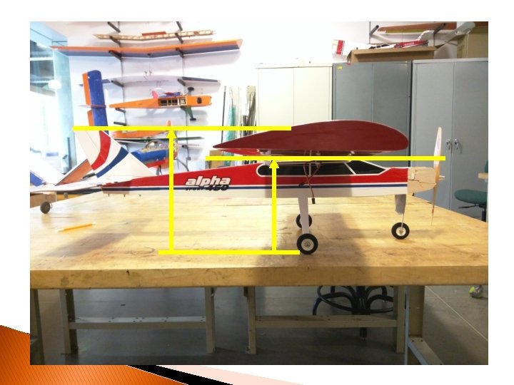
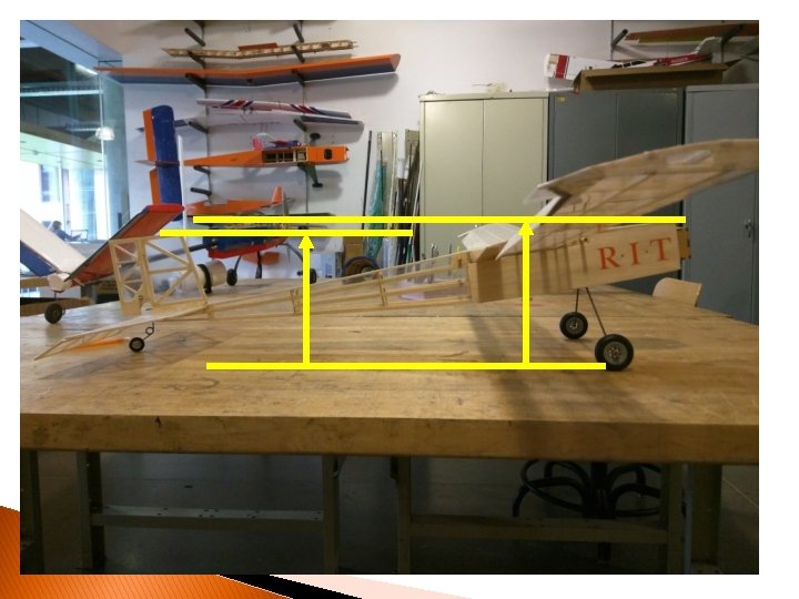
Tail Mounting Bottom Middle Wingbox

Feasibility and Analysis

Testing: Reinforced Trailing Edge Thin trailing edge on S 1223 wing configurations has a high risk of snapping 3 D printed trailing edges would increase strength without too much of a weight increase

Landing Impact An estimate to get the order of magnitude for expected impact loading We will want to design for impacts in the range of a thousand pounds

Bolting Strength An estimate to get the order of magnitude for expected bolting strength in the fuselage We should be able to design for considerable strength

Aerodynamic Wing Design and Sizing: Parameter Selection

Horizontal Stabilizer Design: Parameter Selection

Longitudinal Static Stability Sizing Diagram

Preliminary Fuselage Sizing Diagram: Static Stability and Internal Storage Requirements

Horizontal Stabilizer Design: Overall Geometry

Overall Aircraft Longitudinal Static Stability

Vertical Stabilizer Design: Parameter Selection

Vertical Stabilizer Design: Overall Geometry

Overall Aircraft Directional Static Stability

Updated Take-Off and Landing Performance

Plan for continuing testing

Questions?
- Slides: 37