
P 13651 MPI WAX MELTER MSD I System

- Slides: 24
P 13651: MPI WAX MELTER MSD I: System Design Review
AGENDA v v v v v Team Introduction Project Introduction System Decomposition Customer Needs Concept Generation Concept Selection Risk Management MSD I Work Schedule Question and Answer Session
INTRODUCTION • Team Rachael Hamilton (Chem. E) Michael Blachowicz (ME) Sean Sutton (Chem. E) Alex Kibbe (EE) Valentina Mejia (ME) Jonathan Waldron (EE) • Customer Aaron Phipps, MPI Product Engineer • Support Michael Zona, Project Guide Sarah Brownell, Faculty Champion Project Manager Lead Engineer Project Engineers Edge Expert
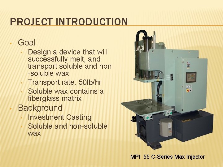
PROJECT INTRODUCTION • Goal • • Design a device that will successfully melt, and transport soluble and non -soluble wax Transport rate: 50 lb/hr Soluble wax contains a fiberglass matrix Background • • Investment Casting Soluble and non-soluble wax MPI 55 C-Series Max Injector
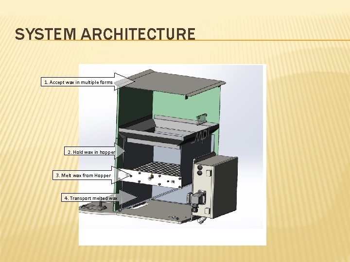
SYSTEM ARCHITECTURE 1. Accept wax in multiple forms 2. Hold wax in hopper 3. Melt wax from Hopper 4. Transport melted wax
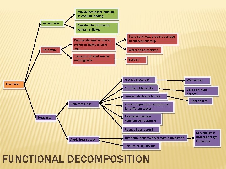
Provide access for manual or vacuum loading Accept Wax Hold Wax Provide inlet for blocks, pellets, or flakes Store solid wax, prevent passage to subsequent step Provide storage for blocks, pellets or flakes of solid wax Water soluble: flakes Transport of solid wax to melting zone Built-in Melt Wax Provide Electricity Wall outlet Condition Electricity Based on heat source Convert electricity to heat Generate Heat Allow temperature adjustments for different waxes Heat source Regulate/maintain constant temperature Heat Wax Reduce heat losses? Apply heat to wax Distribute heat evenly to wax in melt zone Prevent re-solidifying FUNCTIONAL DECOMPOSITION Mechanisms: Induction/High frequency
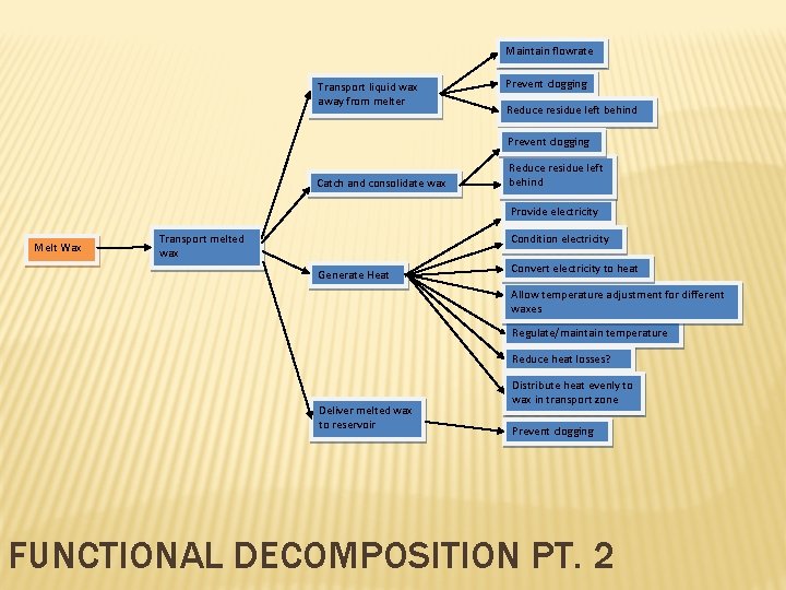
Maintain flowrate Transport liquid wax away from melter Prevent clogging Reduce residue left behind Prevent clogging Catch and consolidate wax Reduce residue left behind Provide electricity Melt Wax Transport melted wax Condition electricity Generate Heat Convert electricity to heat Allow temperature adjustment for different waxes Regulate/maintain temperature Reduce heat losses? Deliver melted wax to reservoir Distribute heat evenly to wax in transport zone Prevent clogging FUNCTIONAL DECOMPOSITION PT. 2
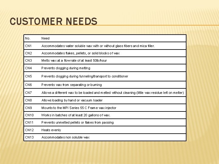
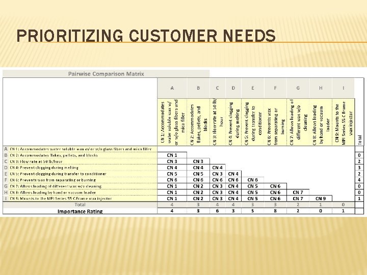
CUSTOMER NEEDS No. Need CN 1 Accommodates water soluble wax with or without glass fibers and mica filler. CN 2 Accommodates flakes, pellets, or solid blocks of wax CN 3 Melts wax at a flow rate of at least 50 lb/hour CN 4 Prevents clogging during melting CN 5 Prevents clogging during funneling/transport to conditioner CN 6 Prevents wax from separating or burning CN 7 Allows a different wax to be loaded and melted without cleaning (little wax residue left on melter) CN 8 Allows loading by hand or vacuum loader CN 9 Mounts to the MPI Series 55 C Frame wax injector CN 10 Works in batches of at least 20 gallons of wax. CN 11 Prevents unmelted pellets or flakes from passing CN 12 Heats evenly CN 13 Accommodates non soluble wax
PRIORITIZING CUSTOMER NEEDS
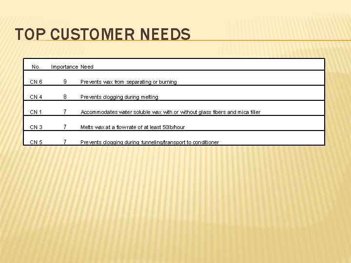
TOP CUSTOMER NEEDS No. Importance Need CN 6 9 Prevents wax from separating or burning CN 4 8 Prevents clogging during melting CN 1 7 Accommodates water soluble wax with or without glass fibers and mica filler CN 3 7 Melts wax at a flow rate of at least 50 lb/hour CN 5 7 Prevents clogging during funneling/transport to conditioner
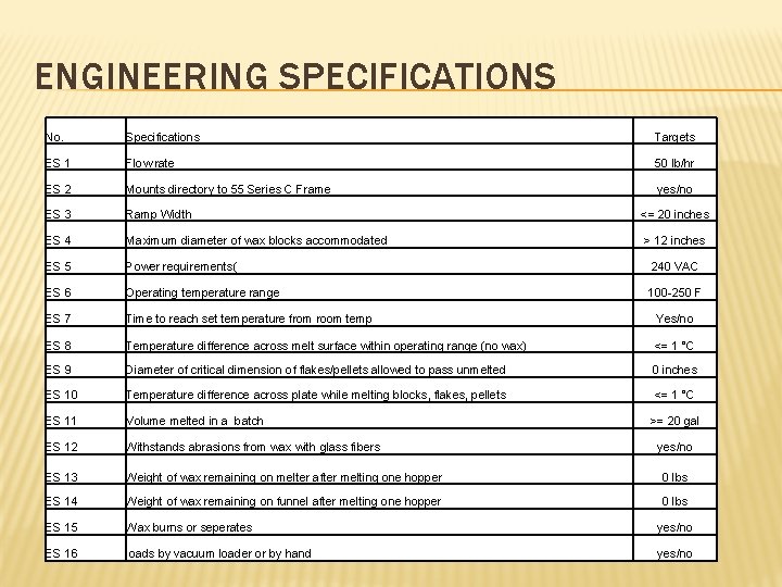
ENGINEERING SPECIFICATIONS No. Specifications Targets ES 1 Flow rate 50 lb/hr ES 2 Mounts directory to 55 Series C Frame yes/no ES 3 Ramp Width <= 20 inches ES 4 Maximum diameter of wax blocks accommodated > 12 inches ES 5 Power requirements( 240 VAC ES 6 Operating temperature range 100 -250 F ES 7 Time to reach set temperature from room temp Yes/no ES 8 Temperature difference across melt surface within operating range (no wax) <= 1 °C ES 9 Diameter of critical dimension of flakes/pellets allowed to pass unmelted 0 inches ES 10 Temperature difference across plate while melting blocks, flakes, pellets <= 1 °C ES 11 Volume melted in a batch ES 12 Withstands abrasions from wax with glass fibers ES 13 Weight of wax remaining on melter after melting one hopper 0 lbs ES 14 Weight of wax remaining on funnel after melting one hopper 0 lbs ES 15 Wax burns or seperates yes/no ES 16 loads by vacuum loader or by hand yes/no >= 20 gal yes/no
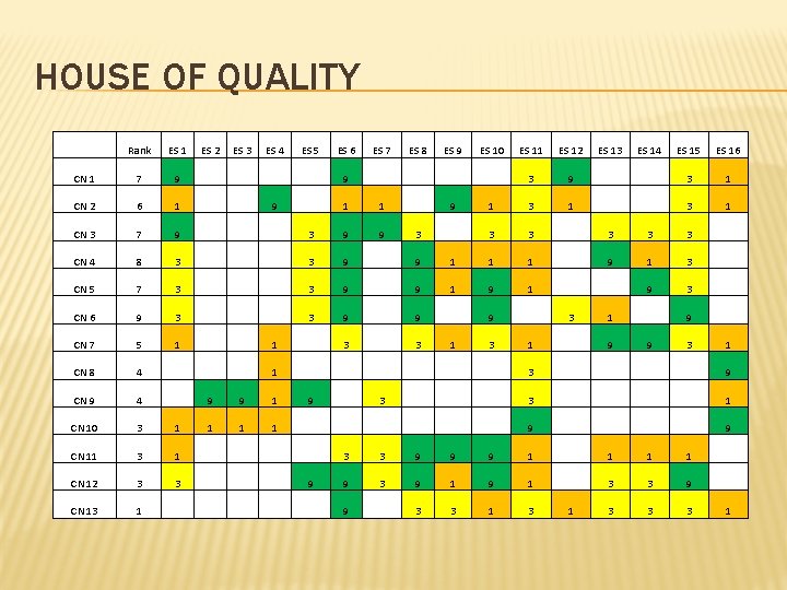
HOUSE OF QUALITY Rank ES 1 ES 2 ES 3 ES 4 ES 5 ES 6 ES 7 ES 8 ES 9 ES 10 ES 11 ES 12 ES 13 ES 14 ES 15 ES 16 CN 1 7 9 3 9 3 1 CN 2 6 1 9 1 1 9 1 3 1 CN 3 7 9 3 9 9 3 3 3 CN 4 8 3 3 9 9 1 1 1 9 1 3 CN 5 7 3 3 9 9 1 9 3 CN 6 9 3 3 9 9 9 3 1 9 CN 7 5 1 1 3 3 1 9 9 3 1 CN 8 4 1 3 9 CN 9 4 9 9 1 9 3 3 1 CN 10 3 1 1 9 CN 11 3 1 3 3 9 9 9 1 1 CN 12 3 3 9 9 3 9 1 3 3 9 CN 13 1 9 3 3 1 3 3 3 1
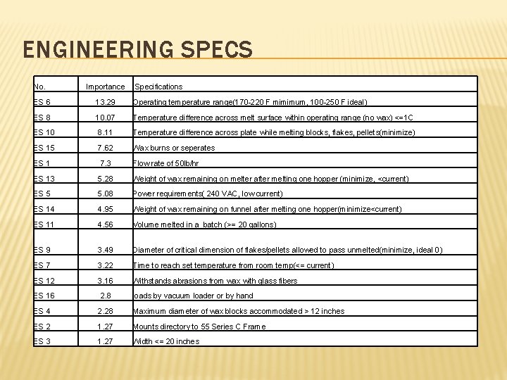
ENGINEERING SPECS No. Importance Specifications ES 6 13. 29 Operating temperature range(170 -220 F mimimum, 100 -250 F ideal) ES 8 10. 07 Temperature difference across melt surface within operating range (no wax) <=1 C ES 10 8. 11 Temperature difference across plate while melting blocks, flakes, pellets(minimize) ES 15 7. 62 Wax burns or seperates ES 1 7. 3 Flow rate of 50 lb/hr ES 13 5. 28 Weight of wax remaining on melter after melting one hopper (minimize, <current) ES 5 5. 08 Power requirements( 240 VAC, low current) ES 14 4. 95 Weight of wax remaining on funnel after melting one hopper(minimize<current) ES 11 4. 56 Volume melted in a batch (>= 20 gallons) ES 9 3. 49 Diameter of critical dimension of flakes/pellets allowed to pass unmelted(minimize, ideal 0) ES 7 3. 22 Time to reach set temperature from room temp(<= current) ES 12 3. 16 Withstands abrasions from wax with glass fibers ES 16 2. 8 loads by vacuum loader or by hand ES 4 2. 28 Maximum diameter of wax blocks accommodated > 12 inches ES 2 1. 27 Mounts directory to 55 Series C Frame ES 3 1. 27 Width <= 20 inches
CONCEPT SELECTION v Key system component: Melt wax v Two main concepts: • • Modified waffle heater wax melter Heated, stirred tank process v Determines choice of other components
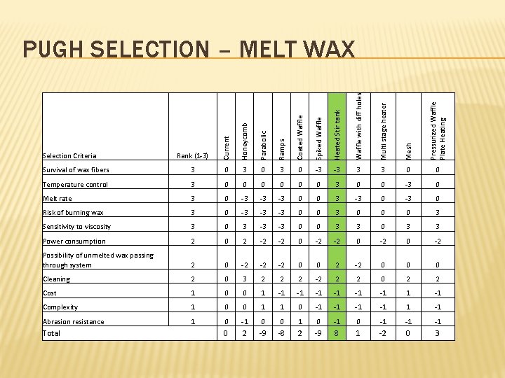
Rank (1 -3) Current Honeycomb Parabolic Ramps Coated Waffle Spiked Waffle Heated Stir tank Waffle with diff holes Multi stage heater Mesh Pressurized Waffle Plate Heating PUGH SELECTION – MELT WAX Survival of wax fibers 3 0 3 0 -3 -3 3 3 0 0 Temperature control 3 0 0 0 3 0 0 -3 0 Melt rate 3 0 -3 -3 -3 0 0 3 -3 0 Risk of burning wax 3 0 -3 -3 -3 0 0 0 3 Sensitivity to viscosity 3 0 3 -3 -3 0 0 3 3 Power consumption 2 0 2 -2 -2 0 -2 Possibility of unmelted wax passing through system 2 0 -2 -2 -2 0 0 0 Cleaning 2 0 3 2 2 2 -2 2 2 0 2 2 Cost 1 0 0 1 -1 -1 -1 Complexity 1 0 0 1 1 0 -1 -1 Abrasion resistance 1 0 -1 0 0 1 0 -1 -1 -1 0 2 -9 -8 2 -9 8 1 -2 0 3 Selection Criteria Total
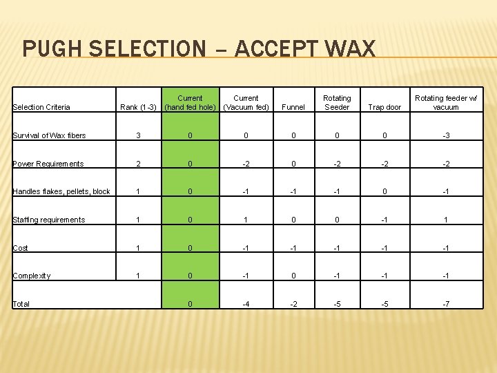
PUGH SELECTION – ACCEPT WAX Selection Criteria Rank (1 -3) Current (hand fed hole) (Vacuum fed) Funnel Rotating Seeder Trap door Rotating feeder w/ vacuum Survival of Wax fibers 3 0 0 0 -3 Power Requirements 2 0 -2 -2 -2 Handles flakes, pellets, block 1 0 -1 -1 -1 0 -1 Staffing requirements 1 0 0 -1 1 Cost 1 0 -1 -1 -1 Complexity 1 0 -1 -1 -1 0 -4 -2 -5 -5 -7 Total
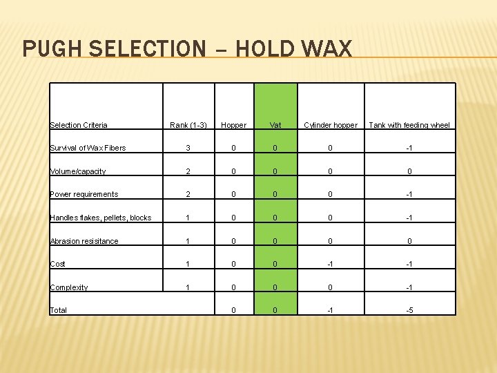
PUGH SELECTION – HOLD WAX Selection Criteria Rank (1 -3) Hopper Vat Cylinder hopper Tank with feeding wheel Survival of Wax Fibers 3 0 0 0 -1 Volume/capacity 2 0 0 Power requirements 2 0 0 0 -1 Handles flakes, pellets, blocks 1 0 0 0 -1 Abrasion resisitance 1 0 0 Cost 1 0 0 -1 -1 Complexity 1 0 0 0 -1 -5 Total
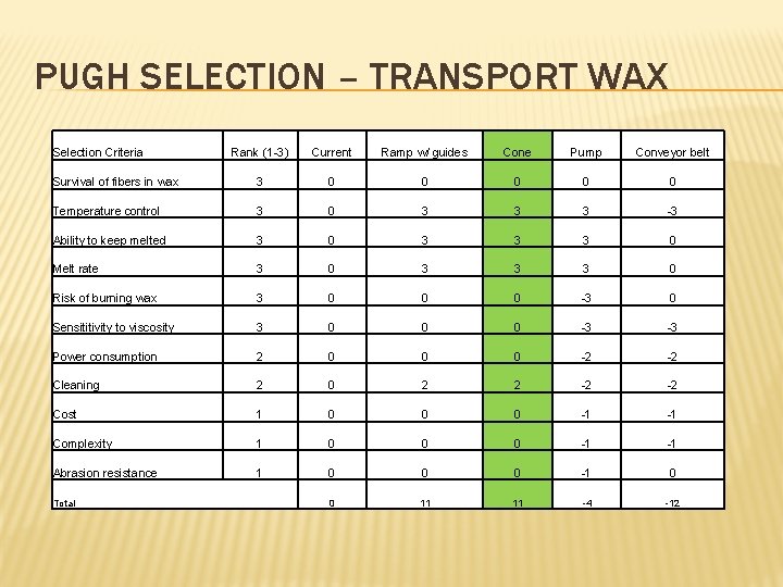
PUGH SELECTION – TRANSPORT WAX Selection Criteria Rank (1 -3) Current Ramp w/ guides Cone Pump Conveyor belt Survival of fibers in wax 3 0 0 0 Temperature control 3 0 3 3 3 -3 Ability to keep melted 3 0 3 3 3 0 Melt rate 3 0 3 3 3 0 Risk of burning wax 3 0 0 0 -3 0 Sensititivity to viscosity 3 0 0 0 -3 -3 Power consumption 2 0 0 0 -2 -2 Cleaning 2 0 2 2 -2 -2 Cost 1 0 0 0 -1 -1 Complexity 1 0 0 0 -1 -1 Abrasion resistance 1 0 0 0 -1 0 0 11 11 -4 -12 Total
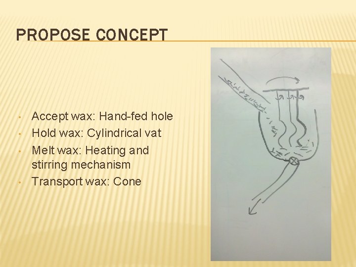
PROPOSE CONCEPT • • Accept wax: Hand-fed hole Hold wax: Cylindrical vat Melt wax: Heating and stirring mechanism Transport wax: Cone
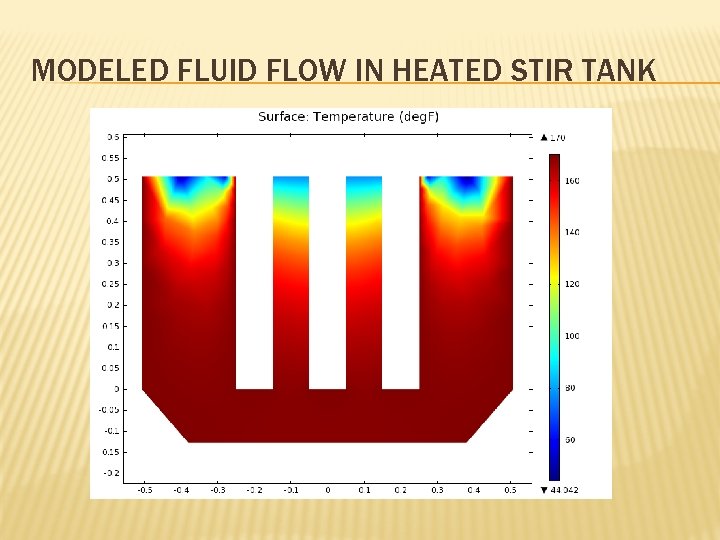
MODELED FLUID FLOW IN HEATED STIR TANK
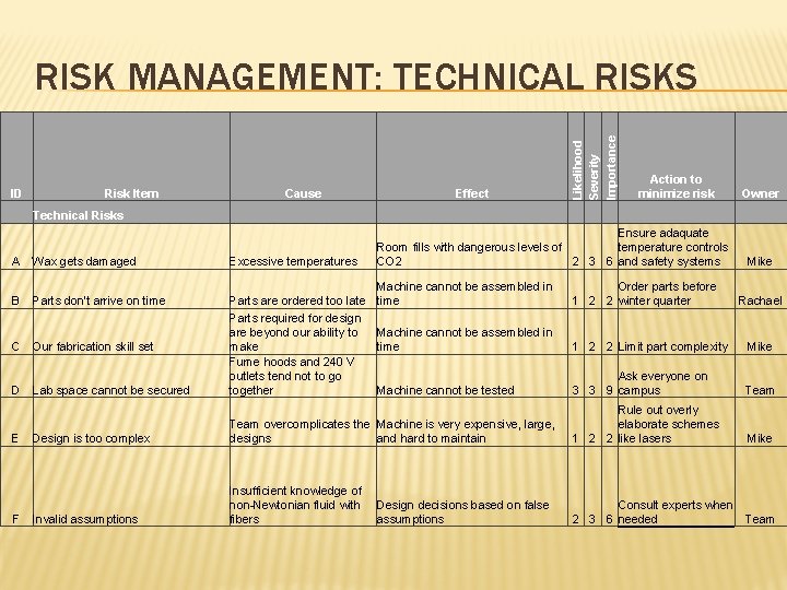
ID Risk Item Cause Technical Risks A Wax gets damaged Excessive temperatures B Parts don't arrive on time C Our fabrication skill set D Lab space cannot be secured Parts are ordered too late Parts required for design are beyond our ability to make Fume hoods and 240 V outlets tend not to go together E F Effect Likelihood Severity Importance RISK MANAGEMENT: TECHNICAL RISKS Action to minimize risk Owner Ensure adaquate temperature controls Room fills with dangerous levels of CO 2 2 3 6 and safety systems Mike Machine cannot be assembled in time Order parts before 1 2 2 winter quarter Machine cannot be assembled in time 1 2 2 Limit part complexity Mike Machine cannot be tested Ask everyone on 3 3 9 campus Team Mike Rachael Design is too complex Team overcomplicates the Machine is very expensive, large, designs and hard to maintain Rule out overly elaborate schemes 1 2 2 like lasers Invalid assumptions Insufficient knowledge of non-Newtonian fluid with fibers Consult experts when 2 3 6 needed Team Design decisions based on false assumptions
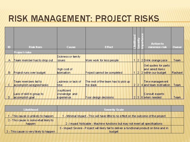
ID Risk Item Cause Project risks A Team member has to drop out Sickness or family issues B C D Effect Likelihood Severity Importance RISK MANAGEMENT: PROJECT RISKS Action to minimize risk Owner More work for less people 1 2 2 Drink orange juice Team Project runs over budget High cost of fabrication Project cannot be completed Get quotes for parts and select items 1 2 2 within our budget Rachael Team members fail to accomplish assigned tasks Laziness or lack of time The rest of the team has to pick up Time management the slack 2 2 4 and team motivation Lack of skill in group to accomplish goal Insufficient knowledge and experience Poor design decisions Team Consult experts 2 3 6 when needed Team Likelihood Severity Scale 1 - This cause is unlikely to happen 2 - This cause is somewhat likely to happen 1 - Minimal Impact - This will have little to no effect on the outcome of the project 3 - This cause is very likely to happen 2 - Impact Noticable - Machine functions but may not meet all specifications 3 - Impact Severe - Project will likely fail to deliver a functional product on time and in budget
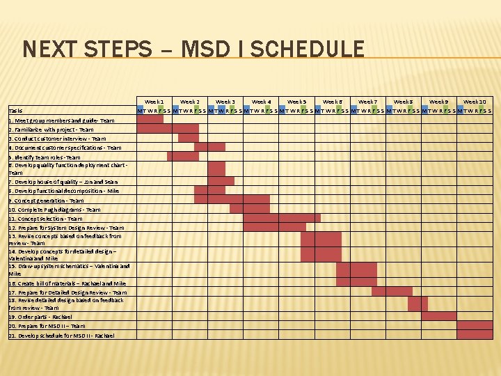
NEXT STEPS – MSD I SCHEDULE Tasks 1. Meet group members and guide- Team 2. Familiarize with project - Team 3. Conduct customer interview - Team 4. Document customer specifications - Team 5. Identify team roles -Team 6. Develop quality function deployment chart - Team 7. Develop house of quality – Jon and Sean 8. Develop functional decomposition - Mike 9. Concept generation - Team 10. Complete Pugh diagrams - Team 11. Concept selection - Team 12. Prepare for System Design Review - Team 13. Revise concepts based on feedback from review - Team 14. Develop concepts for detailed design – Valentina and Mike 15. Draw-up system schematics – Valentina and Mike 16. Create bill of materials – Rachael and Mike 17. Prepare for Detailed Design Review - Team 18. Revise detailed design based on feedback from review - Team 19. Order parts - Rachael 20. Prepare for MSD II – Team 21. Develop schedule for MSD II - Rachael Week 1 Week 2 Week 3 Week 4 Week 5 Week 6 Week 7 Week 8 Week 9 Week 10 MT WR F S S MT WR F S S MT WR F S S
QUESTIONS?