P 10010 MSD IDetail Design Review Motion Tracking


![Questions? Ideas? Concerns? [Source: https: //www. draganfly. com/uav‐helicopter/ draganflyer‐x 6/features/stability. phpg] Motion Tracking Technology Questions? Ideas? Concerns? [Source: https: //www. draganfly. com/uav‐helicopter/ draganflyer‐x 6/features/stability. phpg] Motion Tracking Technology](https://slidetodoc.com/presentation_image/2adc7384c8317687cbed1109ada1dbe4/image-51.jpg)
- Slides: 51

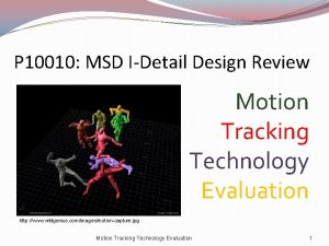
P 10010: MSD I-Detail Design Review Motion Tracking Technology Evaluation http: //www. wildgenius. com/images/motion-capture. jpg Motion Tracking Technology Evaluation 1

Core Team & Roles David Monahan‐ Project Manager (ME) Brian Glod‐ Data Lead (CE) Assis Ngolo – Communication Lead (CE) Jahanavi Gauthaman‐ Sensor Technology Lead (EE) Cory Laudenslager‐ Sensor‐ MCU Interface Lead (EE) James Stern‐ Sensor‐ Human Interface Lead (ME) Motion Tracking Technology Evaluation 2

Assistive Devices Family Biomedical Systems and Technologies Track Assistive Devices • Sponsored by the National Science Foundation (NSF) Nazareth College Physical Therapy Clinic Motion Tracking Technology Evaluation 3

P 10010 Mission Statement To research sensors and implementation methods for portable motion tracking systems capable of measuring patients' range of motion in their natural environments. The primary ranges of motion of interest: Motion of a human limb, where a limb is defined as a 3‐bar linkage, for example: upper leg, lower leg, and foot. Motion of a human's lower back, where lower back is defined as the lumbar region, with 3 points of contact: sacrum, L 1‐L 2, L 3‐L 5. Motion Tracking Technology Evaluation 4

Project Deliverables Design concepts ranked according to customer needs for use by future MSD projects. Analysis of possible solutions for: Sensors, MCUs, ICs, circuitry, communication devices. Work with P 10011 to research compatible enclosures for the system. Testing methods/ fixtures to test future systems. Test several prototype sensors and systems (MSDII) Motion Tracking Technology Evaluation 5

Customer Needs 6

Customer Needs (contd. ) 7

Customer Needs II – P 10011 Body Part Addressed by Spec # Keep each group informed of progres: Each group should understand what the other group is doing, and know how they plan to continue their projects Both E 22 1 Design for multiple sensors: Need to know if there is a need to design around multiple types of sensors Both E 22 P 10011 2 Location of sensors: Need a list of appropriate placement of sensors on body to adhere to comfort styles of each part of the body affected Both E 22 CND P 10011 1 Accuracy of Sensors: Need to know what degree the enclosure can affect the sensor reading and still allow the system to generate meaningful data Both E 25 CNE P 10011 1 Durability: Need to know how well the sensor modules need to be protected by enclosures and how much impact the enclosure must ablate to protect the sensor Both ? CNF P 10011 2 Size: Need a list of sizes of sensor units involved to design enclosures they will fit in Both E 3 CNG P 10011 2 Weight: Need to know approximate or worst case scenario weight to know the maximum weight enclosures can add to system Both E 9, E 12 Need # Category Importance CNA P 10011 1 CNB P 10011 CNC Description Motion Tracking Technology Evaluation 8

Target Customer Specifications Motion Tracking Technology Evaluation 9

Target Customer Specifications (contd. ) Motion Tracking Technology Evaluation 10

System Overview Human Interface (P 10011) Sensors Interface Circuitry Microcontrolle r Unit Storage Interface Signal Amplification Active Filtering Communication Interface [www. serverlab. net] Analog‐to‐Digital Conversion [www. laptoping. com] Motion Tracking Technology Evaluation 11

Motion Tracking Technology Evaluation 12

Sensor Feasibility Overview Spec Customer Design Specification Units Number Need Ideal Value 1 CN 14 Accuracy Degrees ± 1 2 CN 16 Range Degrees 180 3 CN 6 Size of Sensor mm x mm 30 x 15 4 CN 13 Degrees of Freedom Axis 3 7 CN 3 Input Voltage V 9 CN 3 Output Voltage V 3 -5 10 CN 21 Set-up Time Minutes 12 CN 7 Weight of Sensors g 17 CN 7 Comfort of Sensors Subjective on Person 19 CN 28 Patient Safety 20 Cost LIS 302 DL Rank Tilt Sensor Rank DE-ACCM 3 D 2 Rank Atomic IMU Rank Razor IMU Rank Digital Output (1 -10) IMU Board (1 -10) Accelorometer (1 -10) - 6 Do. F (1 -10) Accelorometer Flex Sensor ± 10% 7 ± 10% 7 90 6 180 10 180 8 180 10 10 4. 5 x 3 x 5 9 3 X 5 X 1 10 25 X 20. 4 X 2 10 21 x 10 x 8 10 47 x 37 x 25 4 180 17. 5 x 1 1 5 3 6 3 9 6 10 3. 5 to 15 V (onboard regulator) 2. 4 to 3. 6 (no onboard 10 regulator) 10 3. 4 -10 10 2. 7 -3. 6 10 2 10 Digital (2. 1 -3. 6) 10 5 2. 8 -4 10 Digital 10 2. 5 10 1. 5 -2. 4 10 3. 3 10 10 5 10 15 8 15 8 10 5 g 10 2 10 1. 3 10 15 6 4 10 High 8 High 10 Low 6 High 10 Subjective Patient is Safe 8 Safe 10 Safe 10 Dollars 10 10 125 5 Medium ($35) 8 125 5 89. 95 6 104 100 86 RANK 5 V 9 10 93 Motion Tracking Technology Evaluation 96 101 13

Resistive Response Flex Sensor http: //blog. bioethics. net/spine. gif; http: //mech 207. engr. scu. edu/Sensor. Presentations/Jan%20 -%20 Flex%20 Sensor%20 Combined. pdf; devices. sapp. org/component/flex/ Motion Tracking Technology Evaluation 14

How Position Sensors work (example) Motion Tracking Technology Evaluation 15

DE-ACCM 3 D 2 Buffered ± 2 g Tri-axis Accelerometer 3 axis output in the x, y, and z Sensitive (up to 720 m. V/g) Low power, input voltage, and low current draw Light weight and small Voltage regulator Short protection Limitation: stand‐alone accelerometer http: //www. dimensionengineering. com/datasheets/DE-ACCM 3 D 2. pdf Motion Tracking Technology Evaluation 16

LIS 302 DL Smart Digital Output “Piccolo” Accelerometer 2. 16 V to 3. 6 V supply voltage <1 m. W power consumption +‐ 2 g/+‐ 8 g dynamically selectable full‐ scale I 2 C/SPI digital output interface Embedded high pass filter 10000 g high shock survivability Low cost (~$10) Limitation: stand‐alone accelerometer http: //sites. google. com/site/hardwaremonkey/lis 302 dlaccelerometer Motion Tracking Technology Evaluation 17

Tilt Sensor IMU Board Gyro and Tilt sensor Low Voltage Operation: 5 V Regulated Highly Accurate/High Sensitivity Rated Analog Output Self Test For Both Sensors Small and light weight Cost: $125. 00 Limitations: High cost; Only 2 axis Motion Tracking Technology Evaluation 18

IDG 500/ADXL 335 IMU 5 Degrees of Freedom Accurate Measurement Dual‐axis gyroscope and Triple‐axis accelerometer 0. 1" footprint roll, pitch, and tilt measurements Motion Tracking Technology Evaluation 19

Atomic IMU – 6 Degrees of Freedom �Input: 5 V from MCU Rail �Output: 0 -3. 3 V Digital (UART) �(6) 10 Bit ADCs on Board W/ Programmable Sampling Rates �Uses (1) MMA 7260 Q accelerometer + (3) LISY 300 AL Gyros �Size: 47 x 37 x 25 mm �Cost: $124. 95 Motion Tracking Technology Evaluation 20

Razor‐Ultra‐Thin IMU – 6 Degrees of Freedom �Input: 3. 3 V from MCU Rail �Output: Analog Voltage (Centered at 1. 5 V) �Uses (1) ADXL 335 Accelerometer + (3) Gyros-(2) LPR 530 AL + (1) LY 530 ALH �Size: 15 x 30 x 2 mm �Cost: $89. 95 Motion Tracking Technology Evaluation 21

Feasibility – Rabbit LP 3500 � Size: 2. 60” x 3. 65” x 0. 45” � Power consumption � <20 m. A, 3 VDC at 7. 4 MHz � <100µA sleep mode � ADC inputs � Differential mode � � 4 channels 12‐bit (9‐bit accuracy) � Single‐ended � � LP 3500 [www. rabbit. com] 8 channels 11‐bit (8‐bit accuracy) � Up to 200 samples/sec � Flash: 512 K � SRAM: 512 K � Digital inputs: 16 � Digital outputs: 10 � Cost: $199 for board; $399 for starter kit RCM 3900 [www. rabbit. com]

Feasibility – TI MSP-EXP 430 F 5438 � Power consumption: � 18 MHz – 10 m. A (no LCD); 30 m. A (with LCD) � 1 MHz – 280 µA � Digital I/O: 34 pins � ADC inputs � 5 channels, 12‐bits � Communication � 4 x UART/LIN/Ir. DA/SPI � 4 x I 2 C/SPI � USB � Flash: 256 KB � SRAM: 16 KB � Development software � Free version limits to <4 KB program � No non‐volatile storage (micro. SD/SD) � Cost � $149 for board � $99 for programmer TI MSP-EXP 430 F 5438 [www. ti. com] TI MSP-FET 430 UIF [www. ti. com]

Feasibility – Technologic Systems TS-7800 � Size: unknown � ARM 9 CPU 500 MHz � Supported by GNU GCC [free] � 12, 000 LUT Lattice FPGA � Power consumption: 5 VDC @ 800 m. A � General Purpose I/O: 110 pins � ADC inputs: 5 channels, 10‐bits � Communication � 2 x SATA � 10 RS‐ 232/serial � Ethernet 10/1000 � 2 x USB 2. 0 (480 Mbit/s) � Flash: 512 MB � RAM: 128 MB DDR � Non‐volatile storage � Standard/full SD � micro. SD � Cost � $269 for board � $100 for development kit � ~$10 additional ADCs TS-7800 [www. embeddedarm. com] KIT-ARM Dev Kit [www. embeddedarm. com]

Feasibility – Technologic Systems TS-7500 � Size: 2. 9” x 2. 6” � ARM 9 CPU 250 MHz � Supported by GNU GCC [free] � 5, 000 LUT Lattice FPGA � Power consumption: 5 VDC @ 400 m. A � General Purpose I/O: 33 pins � ADC inputs: 0 � Communication � 8 TTL UART � Ethernet 10/100 � 2 x USB 2. 0 (480 Mbit/s) � Flash: 4 MB � RAM: 64 MB DDR � Non‐volatile storage � micro. SD � Cost � $139 for board � $200 for development kit � ~$10 additional ADCs TS-7500 [www. embeddedarm. com] KIT-ARM Dev Kit [www. embeddedarm. com]

Feasibility –Technologic Systems TS-7260 � Size: 3. 8” x 4. 8” � ARM 9 CPU 200 MHz � Supported by GNU GCC [free] � Power consumption: 5 VDC @ 200 m. A � General Purpose I/O: 30 pins � ADC inputs: 2 channels, 12‐bit � Communication � Ethernet 10/100 � 2 x USB 2. 0 (12 Mbit/s) � Flash: 32 MB � RAM: 32 MB � Non‐volatile storage � micro. SD option +$8 � Cost � $179 for board � $100 for development kit � $8 micro. SD option � ~$10 additional ADCs TS-7260 [www. embeddedarm. com] KIT-ARM Dev Kit [www. embeddedarm. com]

Feasibility – Arduino mega � Size: 4” x 2. 1” � Atmel ATmega 1280 – 16 MHz clock � Power consumption: 7 VDC @ 50 m. A � General Purpose I/O: 54 pins � ADC inputs: 2 x 8 channels, 10‐bit � Communication � 4 UART; SPI; I 2 C Arduino Mega [www. arduino. cc] � USB 2. 0 (480 Mbit/s) � Flash: 128 KB � RAM: 8 KB � Programming � Simple USB A male / USB B male � Free, open source hardware and software � Large community micro. SD shield [www. libelium. com] � Non‐volatile storage � Libelium micro. SD “shield” +$30 � Cost � $50 for board � $30 for micro. SD shield [libelium. com] 2500 m. Ah Li-Ion Battery � $50 for 2500 m. Ah Li‐Ion Battery pack [www. liquidware. com]

ADC with the Arduino MCU • 16 Analog channels at 10 bits of precision • At full precision, the MCU can collect 15 k. HZ of samples • This is roughly 66. 6 microseconds • a 16 channel sweep would then take about 1 milicecond • The ADC channels are split in two sections of 8 channels, so a sweep takes half the amount of time, around 0. 5 milliseconds. • We are aiming for a rate no higher than 200 Hz • The ADC allows for both bipolar and monopolar inputs. We'll use monopolar for simplicity • To each data value will be associated a 16 bit timestamp, which will be reset by software before overflow occurs. • We will thus have data blocks lasting a certain lengths of time. This is good for the case of system malfunction (sensor falling out of place) because not all blocks need to be discarded.

Battery Analysis � Total Max Power Consumption of 372 m. A (300 m. A-MCU, 72 m. A-(3) Atomic IMUs) � Ideal Customer Battery Life: 12 Hours � 7. 4 V/4400 m. AH Lithium Ion Battery Pack � 1. 4 x 2. 75 Inches /. 4 Lbs � Rechargeable � Cost: $36. 00 Motion Tracking Technology Evaluation 29

http: //itp. nyu. edu/physcomp/sensors/Reports/Flex Motion Tracking Technology Evaluation 30

Test Fixture Feasibility Most specifications measurable with standard RIT lab equipment Three outliers Accuracy Degrees of Freedom Range Hence: Needed to identify alternative test methods capable of measuring the three “critical” specifications Motion Tracking Technology Evaluation 31

Test Fixture Feasibility Fixtures identified: P 10007 Spine VICON Biomechatronic Robot Biomechatronic Arm Goniometers Custom Fixture Motion Tracking Technology Evaluation 32

Test Fixture Feasibility Motion Tracking Technology Evaluation 33

Test Plan: Subystems/Equipment Subsystems: Equipment Available: Sensor EE/CE Labs Oscilloscopes, Multimeters, varied Microcontroller resistors and capacitors, Soldering irons, Breadboards, PC, Power Test Fixture Supply, Signal Generator, Software Development Boards Equipment Needed: Programs: Arduino, IDE, Java, Solid. Works, Goniometers Pspice, Altera Test Fixture(s) ME Labs Drill Presses, Mills, Lathes P 10007 Spine Fixture Motion Tracking Technology Evaluation 34

Test Plan: Phases �Device Acquisition (wks 10‐ 11) �Finalize BOM, Establish Plan B for each lab �Component/Device (wks 12‐ 13, 1‐ 2 MSD 2) �Preparation for testing, Component Metrics �Integration (wks 14‐ 15, 3‐ 4 MSD 2) �Combine Sensor/MCU Systems, System Metrics �System Performance (wks 16‐ 19, 5‐ 8 MSD 2) �System Performance & Critical Specifications �Test P 10007 Fixture, Test with P 10011‐ Enclosures �Final Evaluation (wks 20‐ 22, 9‐ 11 MSD 2) �Retrace any needed steps, Final Publication Motion Tracking Technology Evaluation 35

Test Plan: Test Methods Motion Tracking Technology Evaluation 36

Simple Fixture will test accuracy, DOF and range of motion (with current design, possibility of more tests for motion can be added). Sensor will be attached to the fixture with velcro bought from Mc. Master. Simple protractors will measure the rotational angle of the fixture to correlate with what is being read from the sensor.

Simple Fixture Most of the parts on the fixture are being bought from Mc. Master‐Carr, so machining cost and time will be low. The BOM price for the fixture is a high estimate because the material being bought to be machined is priced at a specific dimension which is more expensive then the bulk material ordered by the machine shop. Motion Tracking Technology Evaluation 38

Simple Fixture Motion Tracking Technology Evaluation 39

Test Methods BOM Motion Tracking Technology Evaluation 40

Project Plan Overview Motion Tracking Technology Evaluation 41

Project Plan (page 1) Motion Tracking Technology Evaluation 42

Project Plan (page 2) Motion Tracking Technology Evaluation 43

Project Plan (page 3) Motion Tracking Technology Evaluation 44

Risk Assessment Motion Tracking Technology Evaluation 45

Risk Assessment Motion Tracking Technology Evaluation 46

Risk Assessment Motion Tracking Technology Evaluation 47

What’s Next? Week 10: Design Review with EE professors Finalize BOM Prepare for Project Review End of Quarter Peer Evaluations Week 11 Order parts before MSDII Project Review Motion Tracking Technology Evaluation 48

What’s Next? II MSD 2 Build Test Fixture Begin Testing & Resume Test Plan Evaluate interface between all system components Come up with detailed test plan for testing individual components Motion Tracking Technology Evaluation 49

Unresolved Issues/Concerns Customer Need CNE‐ How to Spec? How to test with sensitive circuit boards Concern: How much skin effects the sensor readings Motion Tracking Technology Evaluation 50
![Questions Ideas Concerns Source https www draganfly comuavhelicopter draganflyerx 6featuresstability phpg Motion Tracking Technology Questions? Ideas? Concerns? [Source: https: //www. draganfly. com/uav‐helicopter/ draganflyer‐x 6/features/stability. phpg] Motion Tracking Technology](https://slidetodoc.com/presentation_image/2adc7384c8317687cbed1109ada1dbe4/image-51.jpg)
Questions? Ideas? Concerns? [Source: https: //www. draganfly. com/uav‐helicopter/ draganflyer‐x 6/features/stability. phpg] Motion Tracking Technology Evaluation 51
 Msd basics review
 160 5th ave new york ny 10010
 Chapter review motion part a vocabulary review answer key
 Msd project clear
 Msd bullying
 Mean square displacement diffusion coefficient
 Msd
Msd Msd menu
 Mousai msd 192 dac
 Cp heat exchanger
 Hasil usg 6 minggu
 Msd i
Msd i Msd propecia 1mg
 Msd suisse
 Msd-970
 Passive rom vs active rom
 Periodic motion formula
 An object in motion stays in motion
 Chapter 2 motion section 1 describing motion answer key
 Describing and measuring motion
 Section 1 describing motion worksheet answer key
 Motion section 1 describing motion answer key
 Motion section 1 describing motion
 Describing and measuring motion answer key
 Linear motion in class test review answers
 Projectile motion review
 Lesson 4 gravity and motion lesson review
 Writ of certiorari ap gov example
 Nader amin-salehi
 Traditional and systematic review venn diagram
 Narrative review vs systematic review
 Digital design review
 Preliminary design review example
 Formal design review
 Critical design review
 Critical design review
 Critical design review
 Cdr critical design review
 Gmp design review
 Billy blue college of design reviews
 Formal design review
 Design review example
 Hair design
 Interim design review
 Final design review
 Weld faults
 Internal design review
 Cable installation design review
 Ebay website design review
 Design review presentation
 Social impact statement for early design review
 Pdr preliminary design review
