OWL TECHNOLOGIES Copenhagen November 2004 2 Design overview

OWL TECHNOLOGIES Copenhagen, November 2004

2 Design overview

Optical design Adaptive, conjugated to pupil; First generation 3 Adaptive, conjugated to 8 km; Second generation

Why a spherical primary / flat secondary ? System Performance Risk & cost Larger corrected field of view than equivalent Ritchey-Chretien Low sensitivity to M 2 decenters Corrector excellent baffling options Secondary mirror an issue with aspherical primary Ø Ø Small M 2 (< 3 -m) very high sensitivity to disturbances Large M 2 (> 3 -m) severe fabrication issue if convex added tube length if concave (Gregorian) All wavefront control functions with 6 surfaces Multi-conjugate AO (2 mirrors 2 - and 4 -m, conjugated to 0, 8 km) Ø Ø Moderately large FOV (0. 5 – 2 arc min) an essential mode Needs re-imaging; OWL provides dual conjugate with 6 surfaces only ! 4 Maintainability: 3, 000 segments, all identical & interchangeable.

Why a spherical primary / flat secondary ? System Performance Risk & cost Use of planetary polishers or large stiff figuring tools Ø Ø Lower segment edge misfigure Stable reference, repeatability of radius of curvature No warping harness Ø Ø Structured blanks possible (Si. C a serious option) Less stringent requirements on blanks internal stresses Segment size up to ~2. 3 -m possible Ø Ø Limited by cost-effective transport in standard container No aspherization weak size-dependence Performance losses Ø 5 Ø Lower throughput than a Ritchey-Chretien (option: enhanced coatings ? ) Higher emissivity (option: single surface corrector for very small field of view ? )

Why a spherical primary / flat secondary ? System Performance Spherical polishing Ø Ø Simple and predictable processes, stable and predictable yield Stable reference (rigid tools) Fast process, high efficiency; OWL polishing tool area = 36 largest GTC tool area ! Simple test set-up Unique matrix no segments matching risk 6 TBC: No edge cutting, polished hexagonal Risk & cost

Segment assembly 7 Total quantity: 3048 + 216 + TBD spares
 Ø Glass segments:")
Actuators - Outline of specifications Load cases (nominal, tension and compression) Ø Glass segments: 0 to 170 kg / actuator Ø Lightweight Si. C segments: 0 to 40 kg / actuator Accuracy Ø Ø 2 stages Position Actuator Concept Coarse stage ± 0. 05 mm. Fine stage ± 5 nm - Goal ± 2 nm Extractor ± 1 mm Stroke Ø Coarse stage 20 mm Ø Fine Stage 0. 5 mm - Goal 1 mm Ø Extractor 150 mm TBC Closed Loop Bandwidth Ø Fine stage 5 Hz - Goal 10 Hz. Ø Coarse stage 0. 1 Hz. Max. cost (unit cost for a production of 10, 000 units) 8 Ø Glass segments: < € 3, 500. Goal < € 2, 500. Ø Si. C segments < € 2, 500, Goal < € 2, 000. -

Position sensors 9 Capacitive, inductive or optical Mounted at segments edges Measurement range 0. 5 mm (TBC) Differential accuracy over full range 5 nm Goal 2 nm Maximum measurement frequency 20 Hz Goal 50 Hz Re-calibration frequency once per week Maximum heat dissipassion TBD (minimize) Maximum unit cost (20, 000 units) € 1, 250. -Goal € 750. -

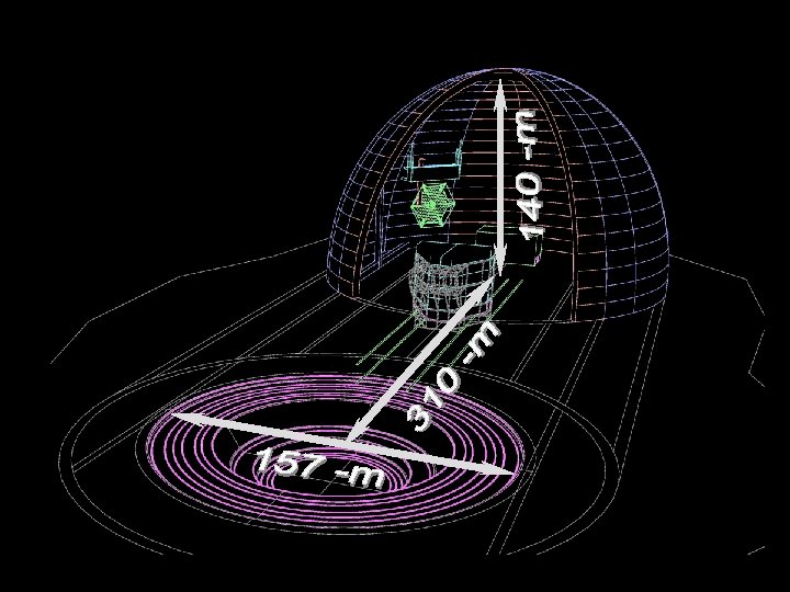
Sliding enclosure M 2 Handling tool M 1 Covers Maintenance facility Azimuth tracks

Altitude bearing Azimuth structure & bogies 12 Altitude tracks
 Altitude cradles & bogies")
Corrector & instrumentation 13 Structure ribs (6 -fold symmetry) Altitude cradles & bogies

All dimensions as multiple of segment size Standardization Ø Ease of integration Ø Ease of maintenance Ø Optimal loads transfers 14 Ø
 lightweight steel structure Ø 14, 800 tons")
Optomechanics Fractal design - Low-cost, Eigenfrequency (Hz) lightweight steel structure Ø 14, 800 tons moving mass (60 times “lighter” than VLT) Mass reduced to ~8, 500 tons with Si. C Ample safety margins (stresses, buckling) Ø 2. 6 Hz locked rotor eigenfrequency Ø Low thermal inertia (developed surface, natural internal air circulation inside structural elements) 15 Ø Differential M 1 -M 2 decenters under gravity Piston Lateral Tilt 3. 4 mm 17. 6 mm 3. 4 arc secs (rigid body motion) Moving mass (t)

16 • Innocuous lateral M 1 -M 2 decenters • Parallelogram-shaped structural modules favour lateral over angular decenters • Lose centring tolerances • Corrector favourably located (stiffness) • Ample design space 20305 Reducing sensitivity by design

Instrument racks 17 6 focal stations; switch by rotating M 6 about telescope axis. Max. instrument mass 15 tons each. Local insulation & air conditioning Issue: needs rigid connection with corrector (TBC).

Controlled optical system Kinematics pointing, compensation for sky rotation encoders, on-sky guide probe Pre-setting bring optical system into linear regime internal, tolerances ~ 1 -2 mm, ~5 arc secs re-position Corrector, M 3 / M 4 / M 5 Phasing keep M 1 and M 2 phased within tolerances Edge sensors, Phasing WFS Segments actuators Metrology: Correction: Field Stabilization Metrology: Correction: Active optics Metrology: Correction: finish off alignment / collimation relax tolerances, control performance & prescription Wavefront sensor(s) Rotation & piston M 5; M 3 & M 4 active deformations Adaptive optics 18 Metrology: Correction: cancel “fast” image motion Guide probe M 6 tip-tilt (flat, exit pupil, 2. 35 -m) atmospheric turbulence, residuals Wavefront sensor(s) M 5, M 6, …
 surfaces within the")
Controlled opto-mechanical system I – Pre-setting Corrector re-centering + 2 (TBC) surfaces within the corrector Internal metrology (e. g. fiber extensometer) Typical accuracy: 10 ppm goal 1 ppm Bandwidth << 1 Hz 19 High operational reliability

Controlled opto-mechanical system II – Kinematics 20 Friction drives Azimuth: 246 units Elevation: 154 units Bandwidth ~0. 5 Hz Fast steering mirror M 6, dia. 2. 35 m Guide probes at technical focus accessible FOV 10’

21 M 6 adaptive & tip-tilt unit

Controlled opto-mechanical system III – Active optics 22 Dual conjugate active optics Deformable M 3 & M 4 VLT-type mirrors Refocus & fine centering 5 Wavefront Sensors at each technical focus (FOV 10’) + feedback AO

Controlled opto-mechanical system IV – Phasing Two segmented mirrors Bandwidth ~5 Hz TBC Edge sensors (capacitive, Inductive or optical) Mach-Zehnder phasing sensor 23 On-sky calibration off-axis
 Complex geometry, But fully predictable Localized signal 24")
Mach-Zehnder calibration sensor Interferogram (ideal conditions) Complex geometry, But fully predictable Localized signal 24 2 k x 2 k camera sufficient for adequate sampling

Piston, Tip, and Tilt: Examples Y – tilts opposite signs X – tilts opposite signs 25 Features Signal Phase Piston only X – tilts same signs Antisymmetry axis Y Antisymmetry axis X Symmetry axis Y

AO Simulations on OWL. 125 sub-apertures across pupil, 11198 actuators on M 6 Bright NGS on-axis, 1 k. Hz frame-rate, ~1 sec of real-life PSF 4 ms coherence time, 0. 5’’ seeing (at 0. 5 mm) OWL pupil + cophasing M 1 & M 2: 35 nm WFE RMS each K band, Strehl ~70% 26 Atmosheric Wavefront Illumination on the pyramid WFS

27 MCAO simulation

28

29

30

2 arc minutes field, l=2. 5 mm 2 adaptive mirrors, 8000 actuators each 3 guide stars 31 Sqrt stretch

Adaptive mirrors 32 LBT – 911 mm diameter, 672 actuators MMT – 642 mm diameter, 336 actuators
 (MMT 336) aspherical shell 642 mm dia. 2")
Adaptive mirrors Capacitive sensors (ref. plate) (MMT 336) aspherical shell 642 mm dia. 2 mm thick Magnets 33 (12 mm diam. )

Extreme AO 34 High performance adaptive optics at visible wavelength Need for 105 -106 actuators MOEMs Time scale : beyond 2015 Some effort going on but need to ramp up Positive factor: limited stroke necessary, large deformable mirrors act as first stage Technology review, design, production & testing of demonstrators foreseen in OWL Phase B
 2015 2019 Prototype OWL 1")
Adaptive Optics Today IR Deformable Mirrors 2008 LBT (JWST) 2015 2019 Prototype OWL 1 st Gen. Diameter 1 -m (2 -m) 0. 3 -m 2 -m 3. 2 -m Actuator spacing 30 mm 15 -25 mm XAO corrector Detector 20 -25 mm Moems/Pzt 256 x 256 ? AO real time control Reference stars 512 x 512 1 kx 1 k Almost OK NGS (LGS) NGS / LGS High sky coverage in the near-IR (better filling of metapupil) Ø LGS needed ~2018; lower number of LGS, Ø Cone effect requires novel approaches e. g. PIGS (Ragazzoni et al) 35 Ø 2 nd Gen.
 Tracking : low concern M 2 flat ! Design insensitive to")
Telescope performance (wind) Tracking : low concern M 2 flat ! Design insensitive to M 2 lateral decenters Ø Structural design privileges M 2 lateral decenter over M 2 tilt Ø Corrector at very stiff location Ø (Pupil shape outdated) DYNAMIC ANALYSIS Worst case. S combined (orientation), 10 m/s, conservative drag coefficients 36 Maximum mean displacements out of worst load cases
 Wind")
Wind 37 MODELLING & TESTING Limited confidence in CFD (Results suspiciously good !) Wind measurements at Jodrell Bank (2004) Wind tunnel testing (2004) Analysis & modelling Courtesy PSP
 ACCELERATED - ACTUAL ELAPSED TIME 150 SECONDS 38 M 1 Corrector")
Wind (pressure distributions) ACCELERATED - ACTUAL ELAPSED TIME 150 SECONDS 38 M 1 Corrector M 2

Wind – design options 1. 2. 3. 4. 5. 6. 7. Higher local stiffness (substructure supporting segments) increases resistance to high spatial frequencies Use of Si. C segments higher M 1 & M 2 bandwidth Embedded variable wind screens (up to z~30 o) Increase M 4 (active mirror) bandwidth ~2 -5 Hz (VLT M 1 support dimensioned for 1 Hz) Increase range of M 6 adaptive correction Operational constraints Site selection 39 … required for AO anyway Variable wind screen embedded in the azimuth structure (notional design); M 2 wind screen not shown
 Diffraction-limited instrumentation (acceptable étendue !) Assumes “friendly")
40 Cost estimate (capital investment, 2002 M€) Diffraction-limited instrumentation (acceptable étendue !) Assumes “friendly site” Ø Average seismicity (0. 2 g) Ø Moderate altitude Ø Average wind speed Ø Moderate investment in infrastructures
 Primary & secondary mirror segments; 1. 8 -m; polished, prices")
Cost estimates (industrial studies) Primary & secondary mirror segments; 1. 8 -m; polished, prices ex works. Si. C (2 suppliers A and B) with overocatings (3 suppliers 1, 2, 3) Glass-Ceramics (2 suppliers C and D) Polishing: 2 suppliers, only one shown (both agree within 10%) 41 Blanks:
 All parts fitting in 40 -ft containers 1. 6")
42 Optimized geometry (interface optics-mechanics) All parts fitting in 40 -ft containers 1. 6 -m all-identical segments (~3000 units), single optical reference for polishing 12. 8 -m standard structural modules (integer multiple of segment size) Friction drive (bogies), hydraulic connection

Cost vs quantity Industrial data Applies to conceptually simple items (e. g. segments, structural nodes) VLT M 1 polishing (4 units) 43 OWL segments (industrial studies)
 comparable to VLT 8 -m production facility")
44 Polishing: factory implementation Size (area) comparable to VLT 8 -m production facility

Meanwhile … 45 ECM BOOSTEC

• Phase C/D approval 2010 • 8 -m mirrors need 6 years First light early 2016 Start of science 2017, 60 m long lead items highly standardized multiple supply lines possible faster integration possible ALTERNATIVE ALLOWING FIRST LIGHT IN 2014 (TBC) IS UNDER EVALUATION 46 BUT:

2020 2015 2010 2005 Timeframe Phase A review ELT Design Study APE on sky Phase B Site selection First light (50 -m) Completion Phase C/D Start of science (60 -m) Groundbreaking 47 Driven by funding, not by technology

Planned studies 2005 - OWL phase A 48 Conceptual design of M 6 adaptive subunit Storage and postprocessing of the Jodrell Bank data Feasibility study for wind tunnel measurements Wind tunnel measurements (Jodrell Bank model) Feasibility study for CFD simulations Dynamic Analysis of M 1 / Corrector M 3 -M 6 Control OWL Instruments Conceptual Design Studies Vibration dampers (local modes) Optimization runs of the mechanical structure I/F with concrete Feasibility study M 4 figuring / CGH Conceptual Design

ELT Design Study The R&D part of a phase B Objectives Ø Ø Technology development towards a European ELT Preparatory work for observatory design Top level requirements Academic & industrial synergy Design-independent Proposal to EC within FP 6 - Approved 49 Ø Ø Ø 39 partners, 47 WPs / Tasks 42 M€ total, 22 M€ requested Timescale 2005 -2008

IAU Symposium 225 - Lausanne, July 2004 Slide 50 ELT Design Study Proposal § The R&D part of a phase B § Objectives – – Technology development towards a European ELT Preparatory work for observatory design Top level requirements Academic & industrial synergy § Design-independent § Proposal to EC within FP 6 - Approved – 39 partners, 47 WPs / Tasks – 42 M€ total, 22 M€ requested – 8 M€ granted – Timescale 2005 -2008 § ESO as coordinator § Contract currently under negotiation with EC
 1")
IAU Symposium 225 - Lausanne, July 2004 Slide 51 Matrix structure WP/Task (47) 1 Participants (39) A B C . . . Z WP budget 2 3 4 5 … 46 47 WP budget WP consol. tool Part. budget Budget prep. tool

IAU Symposium 225 - Lausanne, July 2004 Slide 52 Project Organization

IAU Symposium 225 - Lausanne, July 2004 Slide 53 Shares, in % of total estimated budget ESO

IAU Symposium 225 - Lausanne, July 2004 Slide 54 Engineering WP - overview No 01000 04000 Title Topics Breadboard / prototypes Project Management [includes overall system / project engineering] Wavefront Control Phasing, actuators, metrology, APE, WEB (wind) PSF properties, high contrast imaging, error budgeting 05000 Optical fabrication Si. C, opt. finishing, Al mirrors, coatings 8 x 1 -m Si. C segments 06000 Mechanics Composite materials, Mag. Lev, Friction Drive breadboard Friction drives 07000 Control Support to other WPs (APE, WEB) 08000 Enclosure & infrastr. Enclosure concepts, renewable energies, infrastructures, wind tunnel 09000 Adaptive Optics WFE on 100 -m scale, AO units DM prototypes designs, large DMs, novel concepts, algorithms, simulations 10000 Observ. & science ops. System operations (studies, requirements) 11000 Instrumentation Point designs, ADC 12000 Site characterization Site parameters, measurements, [site testing equipment] modeling, large scale atmo. properties 13000 System layout, Integrated modelling tools, support to analysis & modelling other WPs

From concept to sky testing: APE Active Phasing Experiment Segmenting the VLT Laboratory & on-sky evaluation of up to 3 phasing techniques Integration of phasing into global wavefront control 55 On-sky by 2007

IAU Symposium 225 - Lausanne, July 2004 Slide 56 WEB

IAU Symposium 225 - Lausanne, July 2004 Slide 57 Silicon Carbide prototypes § § § 1 -m class, 8 pcs. , different overcoatings 4 blanks already at ESO Explore overcoating & figuring processes, check for bimetallic effects § Advantages – Stiffer, lighter, better thermo-mechanical properties (than glass) – Higher control bandwidth (position) – Hardness – Lighter, stiffer telescope structure – ~20 years of development, space-qualified – Potentially cost-effective if appropriate design § BUT – Needs qualification for segmented apertures

IAU Symposium 225 - Lausanne, July 2004 Slide 58 Friction drive breadboard Mandatory – Hydraulic pads / tracks not an option ! Alternative: magnetic levitation - TBD

IAU Symposium 225 - Lausanne, July 2004 Slide 59 Overall schedule
 Subject Contact email Design & testing of")
60 ELT Design Study – subcontracts (planned) Subject Contact email Design & testing of 18 segments position actuators E. Brunetto, ESO ebrunett@eso. org Feasibility study for magnetic levitation (telescope kinematics) E. Brunetto, ESO ebrunett@eso. org Conceptual design of opening enclosure for a 50 - and a 100 -m telescope G. Pescador, GRANTECAN German. Pescador@iac. es Wind studies – CFD L. Noethe, ESO M. Quattri, ESO lnoethe@eso. org mquattri@eso. org Wind studies – wind tunnel Idem Site characterization equipment J. Vernin, LUAN vernin@unice. fr

Contacts @ ESO OWL J. Strasser, Telescope Systems Division, Project Controller Ø P. Dierickx, Project Engineer / Manager Ø R. Gilmozzi, Prime Investigator Ø E. Brunetto Optomechanics Ø jstrasse@eso. org pdierick@eso. org rgilmozz@eso. org ebrunett@eso. org ELT Design Study P. Dierickx Project Manager Ø R. Gilmozzi Ø Project Coordinator 61 Ø pdierick@eso. org rgilmozz@eso. org
- Slides: 61