Overview of the 3 DOF Parallel Architecture Wrist


- Slides: 24
Overview of the 3 DOF Parallel. Architecture Wrist Mechanism Stephen Canfield, Professor Department of Mechanical Engineering Tennessee Technological University November 10, 2008
Overview
About Parallel Mechanisms o o o Multiple load-bearing chains b/n output and base Kinematics Advantages n o Stronger, lighter Disadvantages n Reduced range of motion, kinematics
About the PAW o o 3 -5 R Spatial Parallel-architecture mechanism 3 dof n Pitch, yaw, plunge
Characteristics of the PAW o o o o High payload-to-weight, good dynamic performance Ground-relative actuation All-revolute design Closed-form forward/inverse kinematics exist Large range of motion in orientation Singularity free workspace (interior), greater than hemisphere Removes constraint on control algorithms Improved dexterity
Advantages of proposed design o Parallel-architecture: High payload, accuracy, good dynamic performance in light-weight system Large, singularity-free range of motion Eliminate need for slip-rings Provide accuracy needed for solar concentrators Inherently redundant system o - Application for pointing solar arrays – Video o o
Gimbal Kinematics, Options
Past applications Robotic end-effector, compliant design for pointing mirrors, sub 10 nm precision manipulator
Point Design Applications: Thruster
Part Layout
Thruster as built
Application for pointing thruster
Design Point: Solar-Array Mount
Solary Array Mount
Solar Array Mount Description Mass/ Workspace Motor Drive: Maxon EC 90 Flat Motor 1. 5 lb Drive reduction Harmonic Drive HDC 1 M 2. 6 lb Bearings Bronze bushings, ¾, 3/8 ID Shaft 440 c SS Link components 7075 Al Mechanism weight * (without actuation) 14. 75 lb 3 D Mechanism weight (with actuation, includes a 20% factor) 32. 5 lb Working Volume* 5. 5 inch radius cylinder Height is selectable 5. 5 inch cylinder Stowed Volume* 3 high x 7 radius cylinder (inches) 7 x 3 inch cylinder Component Table I: Summary of 3 D solar-array tracking mechanism
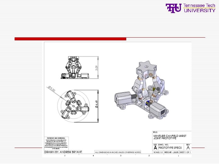
Miniature Gimbal:
Compliant mechanism applications High precision compact design From known topology Conventional 3 dof manipulator (pointing task) Compliant 3 dof manipulator Compact, 6 dof compliant manipulator
Kinematics
Force Analysis o Closed-form kinetostatic analysis Beta=30 degrees Beta=60 degrees
Path planning and trajectory control
Embedded electronics o o o Currently Motorola S-12 family MCU IK ~ 12 k in HCS-12 CPU assembly (unoptimized) 8 channel PWM, Quadrature encoders, drivers
Summary