
Overview of 3 D Graphics Programming Henry Wise
- Slides: 20
Overview of 3 D Graphics Programming Henry Wise Wood Math Club March 12, 2012
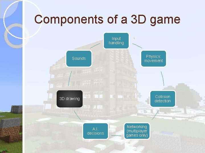
Components of a 3 D game Input handling Physics: movement Sounds Collision detection 3 D drawing A. I. decisions Networking (multiplayer games only)
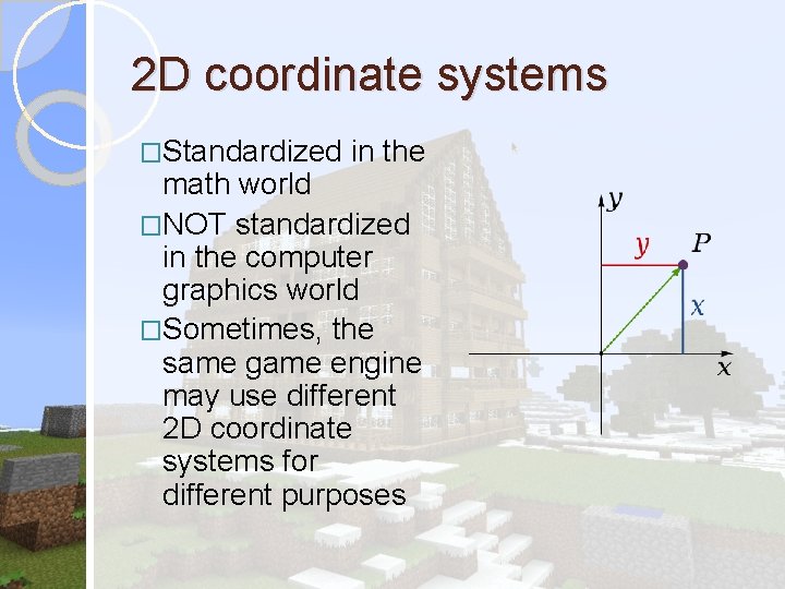
2 D coordinate systems �Standardized in the math world �NOT standardized in the computer graphics world �Sometimes, the same game engine may use different 2 D coordinate systems for different purposes
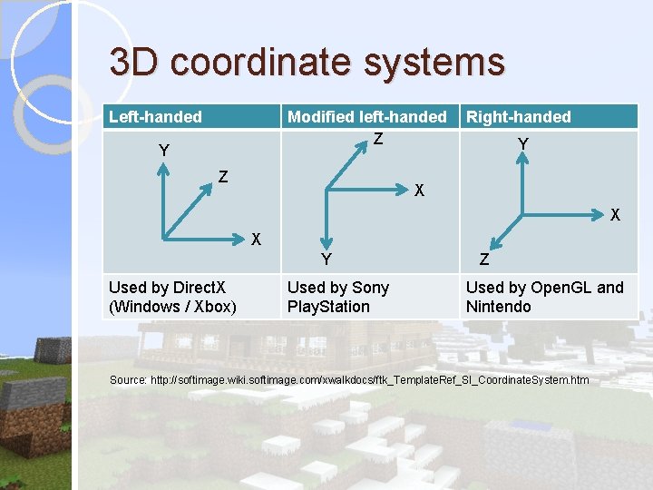
3 D coordinate systems Left-handed Modified left-handed Z Y Z Right-handed Y X X X Y Used by Direct. X (Windows / Xbox) Used by Sony Play. Station Z Used by Open. GL and Nintendo Source: http: //softimage. wiki. softimage. com/xwalkdocs/ftk_Template. Ref_SI_Coordinate. System. htm
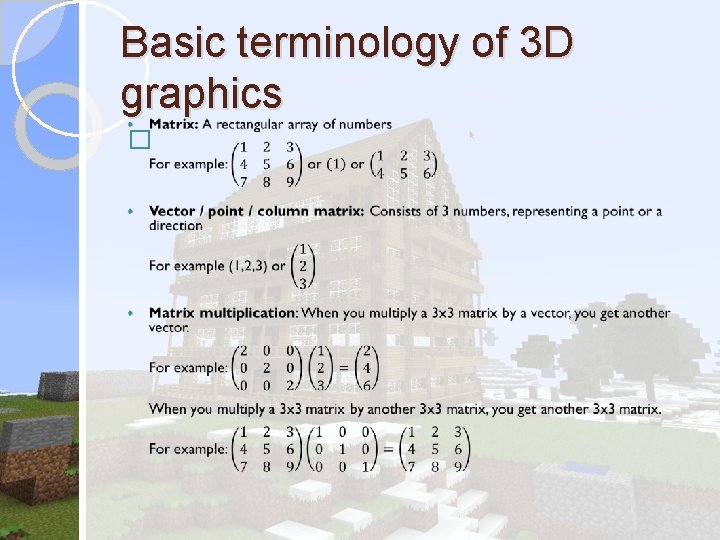
Basic terminology of 3 D graphics �
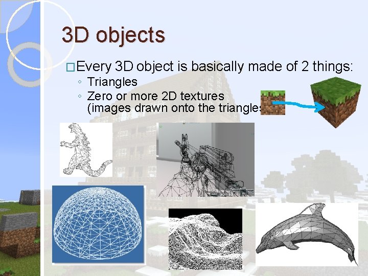
3 D objects �Every 3 D object is basically made of 2 things: ◦ Triangles ◦ Zero or more 2 D textures (images drawn onto the triangles)
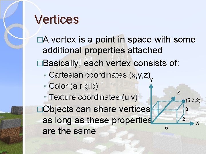
Vertices �A vertex is a point in space with some additional properties attached �Basically, each vertex consists of: ◦ Cartesian coordinates (x, y, z) Y ◦ Color (a, r, g, b) ◦ Texture coordinates (u, v) can share vertices as long as these properties are the same Z (5, 3, 2) �Objects 3 2 5 X
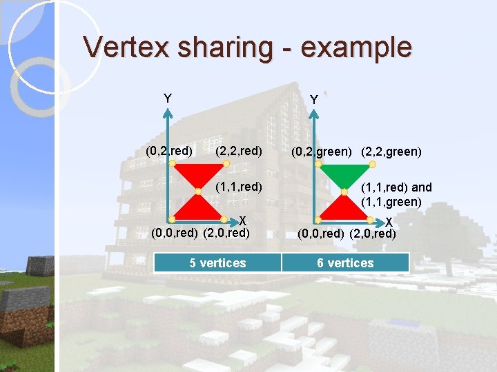
Vertex sharing - example Y Y (0, 2, red) (2, 2, red) (1, 1, red) X (0, 0, red) (2, 0, red) 5 vertices (0, 2, green) (2, 2, green) (1, 1, red) and (1, 1, green) X (0, 0, red) (2, 0, red) 6 vertices
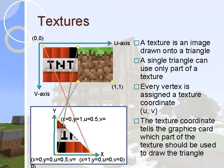
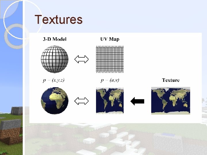
Textures (0, 0) U-axis � A (1, 1) V-axis Y (x=0, y=1, u=0. 5, v= 1) X (x=0, y=0, u=0. 5, v= (x=1, y=0, u=0, v=0) texture is an image drawn onto a triangle � A single triangle can use only part of a texture � Every vertex is assigned a texture coordinate (u, v) � The texture coordinate tells the graphics card which part of the texture should be used to draw the triangle
Textures
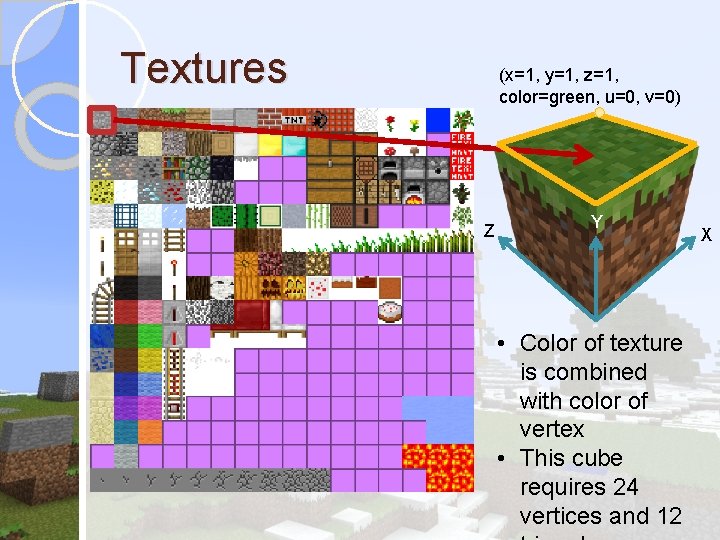
Textures (x=1, y=1, z=1, color=green, u=0, v=0) Z Y • Color of texture is combined with color of vertex • This cube requires 24 vertices and 12 X
Graphics pipeline � The process by which 3 D objects are drawn is known as the graphics pipeline � There are two main types of graphics pipelines: fixed-function and shader � Fixed-function: The graphics card performs a fixed series of steps to render the scene � Shader: The programmer writes a program (shader) that runs on the graphics card to render the scene. Using shaders, you can create more realistic effects like water ripples/reflection � Side note: Shaders have many uses outside of 3 D graphics, where they can be used to perform general computing tasks (e. g. Nvidia CUDA and Open. CL)
Fixed-function vertex pipeline Simplified overview of steps 1. The vertices are multiplied by the world matrix, which transforms each vertex into its correct position 2. The vertices are multiplied by the projection matrix, which converts each 3 D vertex into a 2 D vertex to be displayed on the screen 3. Each triangle is rendered with its corresponding texture, using depth testing to determine which triangles are on top of others
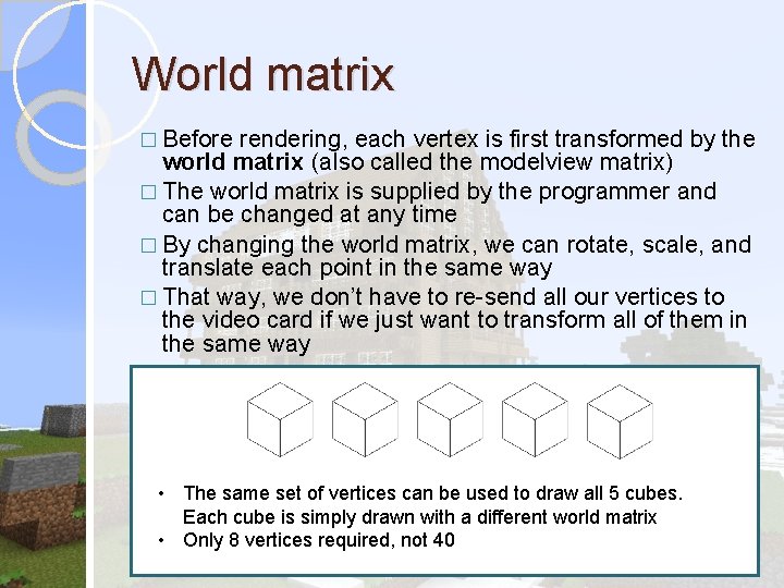
World matrix � Before rendering, each vertex is first transformed by the world matrix (also called the modelview matrix) � The world matrix is supplied by the programmer and can be changed at any time � By changing the world matrix, we can rotate, scale, and translate each point in the same way � That way, we don’t have to re-send all our vertices to the video card if we just want to transform all of them in the same way • The same set of vertices can be used to draw all 5 cubes. Each cube is simply drawn with a different world matrix • Only 8 vertices required, not 40
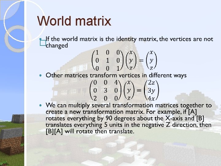
World matrix �
World matrix: Camera �To implement a camera, we have to move all the objects in the opposite of the direction of the camera using the world matrix �For example, if the camera rotates to the right, we have to rotate all of the vertices towards the left
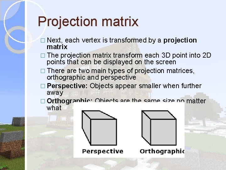
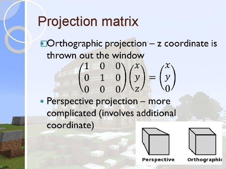
Projection matrix � Next, each vertex is transformed by a projection matrix � The projection matrix transform each 3 D point into 2 D points that can be displayed on the screen � There are two main types of projection matrices, orthographic and perspective � Perspective: Objects appear smaller when further away � Orthographic: Objects are the same size no matter what
Projection matrix �
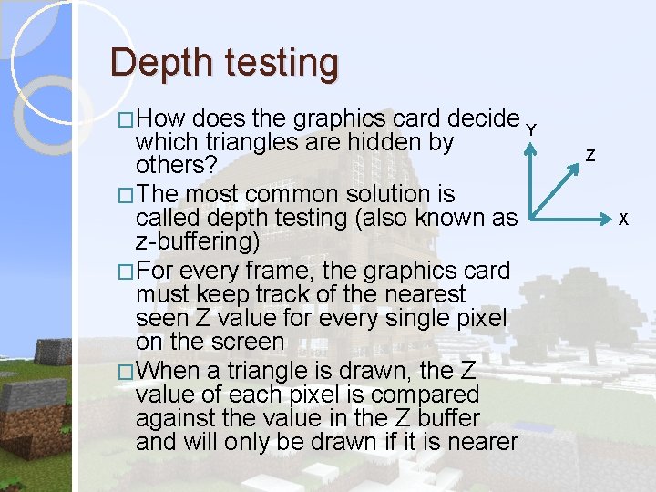
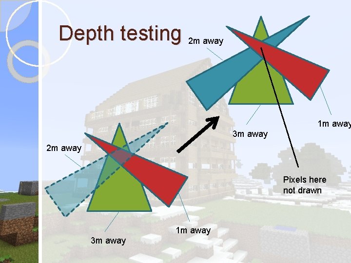
Depth testing �How does the graphics card decide Y which triangles are hidden by others? �The most common solution is called depth testing (also known as z-buffering) �For every frame, the graphics card must keep track of the nearest seen Z value for every single pixel on the screen �When a triangle is drawn, the Z value of each pixel is compared against the value in the Z buffer and will only be drawn if it is nearer Z X
Depth testing 2 m away 1 m away 3 m away 2 m away Pixels here not drawn 1 m away 3 m away