
Overview Instruction level parallelism Problems that limit ILP
Overview • Instruction level parallelism • Problems that limit ILP – Programs – Processor • Simple compiler techniques to increase ILP – Basic pipeline scheduling – Loop unrolling • Dynamic Scheduling Techniques – Scoreboarding – Tomasulo’s Algorithm
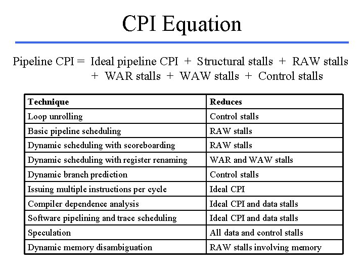
CPI Equation Pipeline CPI = Ideal pipeline CPI + Structural stalls + RAW stalls + WAR stalls + WAW stalls + Control stalls Technique Reduces Loop unrolling Control stalls Basic pipeline scheduling RAW stalls Dynamic scheduling with scoreboarding RAW stalls Dynamic scheduling with register renaming WAR and WAW stalls Dynamic branch prediction Control stalls Issuing multiple instructions per cycle Ideal CPI Compiler dependence analysis Ideal CPI and data stalls Software pipelining and trace scheduling Ideal CPI and data stalls Speculation All data and control stalls Dynamic memory disambiguation RAW stalls involving memory
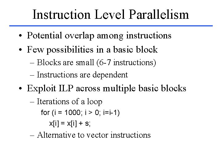
Instruction Level Parallelism • Potential overlap among instructions • Few possibilities in a basic block – Blocks are small (6 -7 instructions) – Instructions are dependent • Exploit ILP across multiple basic blocks – Iterations of a loop for (i = 1000; i > 0; i=i-1) x[i] = x[i] + s; – Alternative to vector instructions
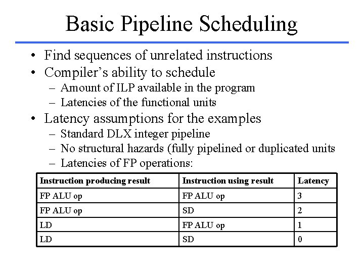
Basic Pipeline Scheduling • Find sequences of unrelated instructions • Compiler’s ability to schedule – Amount of ILP available in the program – Latencies of the functional units • Latency assumptions for the examples – Standard DLX integer pipeline – No structural hazards (fully pipelined or duplicated units – Latencies of FP operations: Instruction producing result Instruction using result Latency FP ALU op 3 FP ALU op SD 2 LD FP ALU op 1 LD SD 0
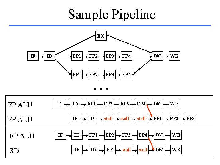
Sample Pipeline EX IF ID FP 1 FP 2 FP 3 FP 4 DM WB . . . FP ALU IF FP ALU SD IF ID FP 1 FP 2 FP 3 FP 4 DM WB IF ID stall FP 1 FP 2 ID FP 1 FP 2 FP 3 FP 4 DM WB IF ID EX stall DM WB FP 3
![Basic Scheduling for (i = 1000; i > 0; i=i-1) x[i] = x[i] +](http://slidetodoc.com/presentation_image_h2/1bb37380b00972a78a459801e80ce9b0/image-6.jpg "Basic Scheduling for (i = 1000; i > 0; i=i-1) x[i] = x[i] +")
Basic Scheduling for (i = 1000; i > 0; i=i-1) x[i] = x[i] + s; Pipelined execution: Loop: LD F 0, 0(R 1) stall ADDD F 4, F 0, F 2 stall SD 0(R 1), F 4 SUBI R 1, #8 stall BNEZ R 1, Loop stall 1 2 3 4 5 6 7 8 9 10 Sequential DLX Assembly Code Loop: LD ADDD SD SUBI BNEZ F 0, 0(R 1) F 4, F 0, F 2 0(R 1), F 4 R 1, #8 R 1, Loop Scheduled pipelined execution: Loop: LD F 0, 0(R 1) 1 SUBI R 1, #8 2 ADDD F 4, F 0, F 2 3 stall 4 BNEZ R 1, Loop 5 SD 8(R 1), F 4 6
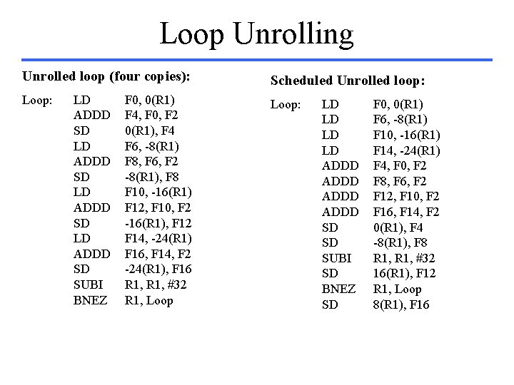
Loop Unrolling Unrolled loop (four copies): Scheduled Unrolled loop: Loop: LD ADDD SD SUBI BNEZ F 0, 0(R 1) F 4, F 0, F 2 0(R 1), F 4 F 6, -8(R 1) F 8, F 6, F 2 -8(R 1), F 8 F 10, -16(R 1) F 12, F 10, F 2 -16(R 1), F 12 F 14, -24(R 1) F 16, F 14, F 2 -24(R 1), F 16 R 1, #32 R 1, Loop LD LD ADDD SD SD SUBI SD BNEZ SD F 0, 0(R 1) F 6, -8(R 1) F 10, -16(R 1) F 14, -24(R 1) F 4, F 0, F 2 F 8, F 6, F 2 F 12, F 10, F 2 F 16, F 14, F 2 0(R 1), F 4 -8(R 1), F 8 R 1, #32 16(R 1), F 12 R 1, Loop 8(R 1), F 16
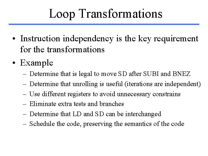
Loop Transformations • Instruction independency is the key requirement for the transformations • Example – – – Determine that is legal to move SD after SUBI and BNEZ Determine that unrolling is useful (iterations are independent) Use different registers to avoid unnecessary constrains Eliminate extra tests and branches Determine that LD and SD can be interchanged Schedule the code, preserving the semantics of the code
Dependences • If instructions are independent – They are parallel – They can be reordered • Types of dependences – Data – Name – Control
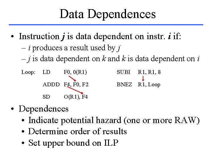
Data Dependences • Instruction j is data dependent on instr. i if: – i produces a result used by j – j is data dependent on k and k is data dependent on i Loop: LD F 0, 0(R 1) ADDD F 4, F 0, F 2 SD SUBI R 1, 8 BNEZ R 1, Loop O(R 1), F 4 • Dependences • Indicate potential hazard (one or more RAW) • Determine order of results • Set upper bound on ILP

Techniques to Increase ILP • Dependences are a property of programs • Actual hazards are a property of the pipeline • Techniques to avoid dependence limitations – Maintain dependences but avoid hazards • Code scheduling – hardware – software – Eliminate dependences by code transformations • Complex • Compiler-based
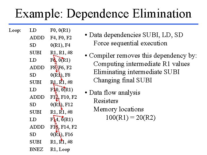
Example: Dependence Elimination Loop: LD ADDD SD SUBI BNEZ F 0, 0(R 1) F 4, F 0, F 2 0(R 1), F 4 R 1, #8 F 6, 0(R 1) F 8, F 6, F 2 0(R 1), F 8 R 1, #8 F 10, 0(R 1) F 12, F 10, F 2 0(R 1), F 12 R 1, #8 F 14, 0(R 1) F 16, F 14, F 2 0(R 1), F 16 R 1, #8 R 1, Loop • Data dependencies SUBI, LD, SD Force sequential execution • Compiler removes this dependency by: Computing intermediate R 1 values Eliminating intermediate SUBI Changing final SUBI • Data flow analysis Resisters Memory locations 100(R 1) = 20(R 2)
Name Dependences • Two instructions use the same register or memory location, but there is no flow of data • Antidependence – Corresponds to a WAR hazard • Output Dependence – Corresponds to a WAW hazard • To eliminate the dependence: change the name! – Register renaming (easy) • Static or dynamic
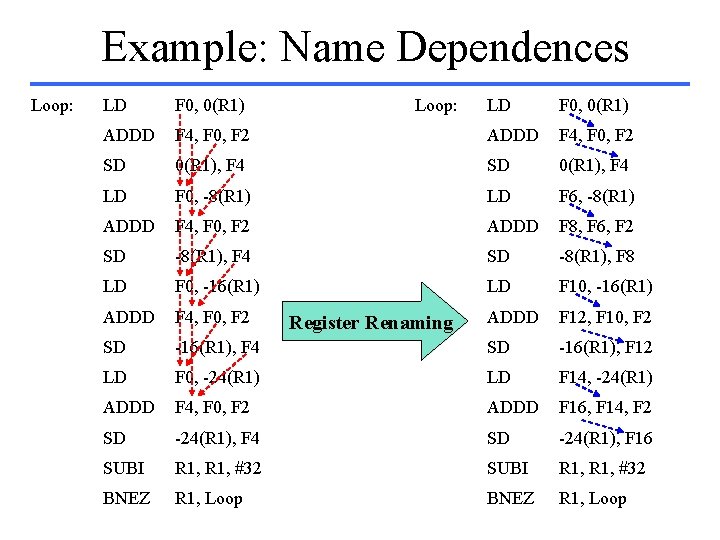
Example: Name Dependences Loop: LD F 0, 0(R 1) ADDD Loop: LD F 0, 0(R 1) F 4, F 0, F 2 ADDD F 4, F 0, F 2 SD 0(R 1), F 4 LD F 0, -8(R 1) LD F 6, -8(R 1) ADDD F 4, F 0, F 2 ADDD F 8, F 6, F 2 SD -8(R 1), F 4 SD -8(R 1), F 8 LD F 0, -16(R 1) LD F 10, -16(R 1) ADDD F 4, F 0, F 2 ADDD F 12, F 10, F 2 SD -16(R 1), F 4 SD -16(R 1), F 12 LD F 0, -24(R 1) LD F 14, -24(R 1) ADDD F 4, F 0, F 2 ADDD F 16, F 14, F 2 SD -24(R 1), F 4 SD -24(R 1), F 16 SUBI R 1, #32 BNEZ R 1, Loop Register Renaming
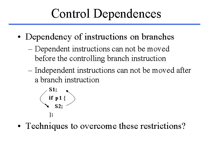
Control Dependences • Dependency of instructions on branches – Dependent instructions can not be moved before the controlling branch instruction – Independent instructions can not be moved after a branch instruction S 1; if p 1 { S 2; }; • Techniques to overcome these restrictions?
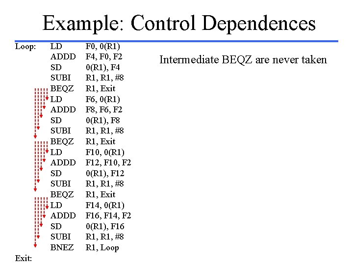
Example: Control Dependences Loop: Exit: LD ADDD SD SUBI BEQZ LD ADDD SD SUBI BNEZ F 0, 0(R 1) F 4, F 0, F 2 0(R 1), F 4 R 1, #8 R 1, Exit F 6, 0(R 1) F 8, F 6, F 2 0(R 1), F 8 R 1, #8 R 1, Exit F 10, 0(R 1) F 12, F 10, F 2 0(R 1), F 12 R 1, #8 R 1, Exit F 14, 0(R 1) F 16, F 14, F 2 0(R 1), F 16 R 1, #8 R 1, Loop Intermediate BEQZ are never taken
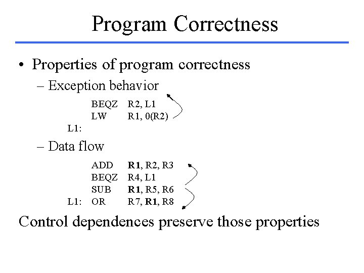
Program Correctness • Properties of program correctness – Exception behavior BEQZ R 2, L 1 LW R 1, 0(R 2) L 1: – Data flow ADD BEQZ SUB L 1: OR R 1, R 2, R 3 R 4, L 1 R 1, R 5, R 6 R 7, R 1, R 8 Control dependences preserve those properties
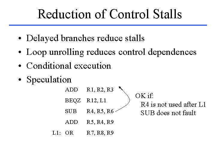
Reduction of Control Stalls • • Delayed branches reduce stalls Loop unrolling reduces control dependences Conditional execution Speculation ADD R 1, R 2, R 3 BEQZ R 12, L 1 SUB R 4, R 5, R 6 ADD R 5, R 4, R 9 L 1: OR R 7, R 8, R 9 OK if: R 4 is not used after L 1 SUB does not fault
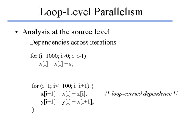
Loop-Level Parallelism • Analysis at the source level – Dependencies across iterations for (i=1000; i>0; i=i-1) x[i] = x[i] + s; for (i=1; i<=100; i=i+1) { x[i+1] = x[i] + z[i]; y[i+1] = y[i] + x[i+1]; } /* loop-carried dependence */
![Loop-Carried Dependences for (i=1; i<=100; i=i+1) { x[i] = x[i] + y[i]; y[i+1] =](http://slidetodoc.com/presentation_image_h2/1bb37380b00972a78a459801e80ce9b0/image-20.jpg "Loop-Carried Dependences for (i=1; i<=100; i=i+1) { x[i] = x[i] + y[i]; y[i+1] =")
Loop-Carried Dependences for (i=1; i<=100; i=i+1) { x[i] = x[i] + y[i]; y[i+1] = w[i] + z[i]; } Non-circular dependences x[1] = x[1] + y[1]; for (i=1; i<=99; i=i+1) { y[i+1] = w[i] + z[i]; x[i+1] = x[i +1] + y[i +1]; } y[101] = w[100] + z[100];
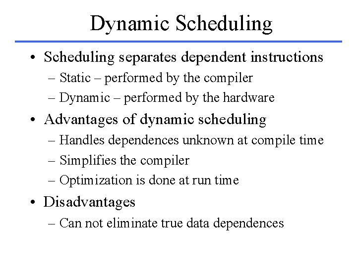
Dynamic Scheduling • Scheduling separates dependent instructions – Static – performed by the compiler – Dynamic – performed by the hardware • Advantages of dynamic scheduling – Handles dependences unknown at compile time – Simplifies the compiler – Optimization is done at run time • Disadvantages – Can not eliminate true data dependences
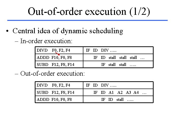
Out-of-order execution (1/2) • Central idea of dynamic scheduling – In-order execution: DIVD F 0, F 2, F 4 IF ID DIV …. . ADDD F 10, F 8 IF ID stall … SUBD F 12, F 8, F 14 IF stall …. . – Out-of-order execution: DIVD F 0, F 2, F 4 SUBD F 12, F 8, F 14 ADDD F 10, F 8 IF ID DIV …. . IF ID A 1 A 2 A 3 A 4 … IF ID stall …. .
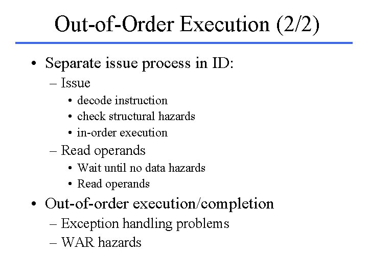
Out-of-Order Execution (2/2) • Separate issue process in ID: – Issue • decode instruction • check structural hazards • in-order execution – Read operands • Wait until no data hazards • Read operands • Out-of-order execution/completion – Exception handling problems – WAR hazards
DS with a Scoreboard • Allow out-of-order execution – Sufficient resources – No data dependencies • Responsible for issue, execution and hazards • Functional units with long delays – Duplicated – Fully pipelined • CDC 6600 – 16 functional units
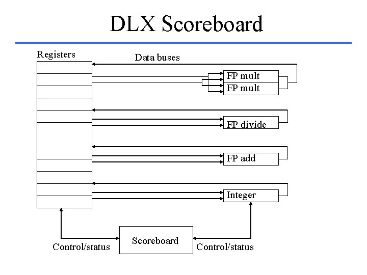
DLX Scoreboard Registers Data buses FP mult FP divide FP add Integer Control/status Scoreboard Control/status
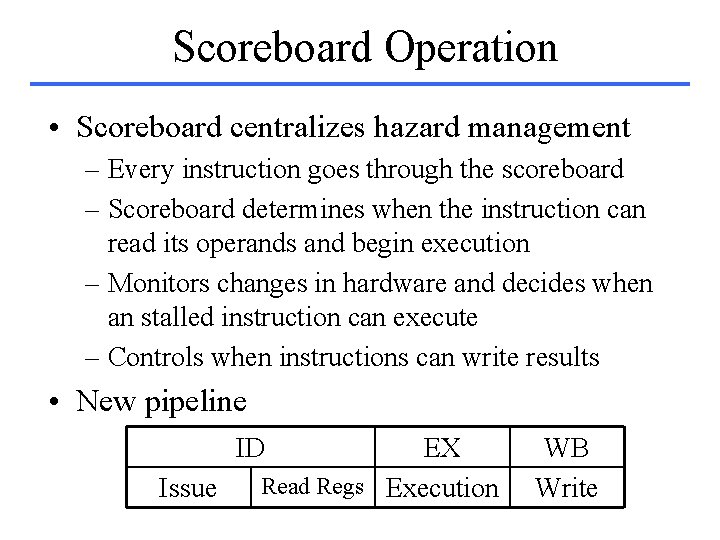
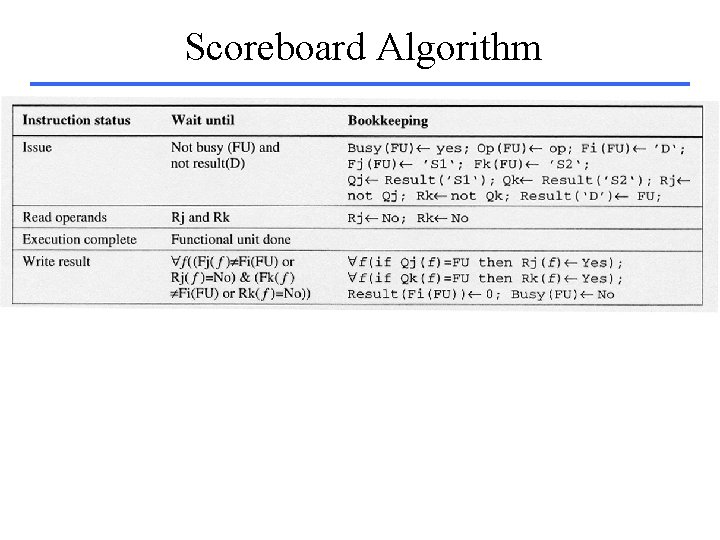
Scoreboard Operation • Scoreboard centralizes hazard management – Every instruction goes through the scoreboard – Scoreboard determines when the instruction can read its operands and begin execution – Monitors changes in hardware and decides when an stalled instruction can execute – Controls when instructions can write results • New pipeline ID Issue EX Read Regs Execution WB Write
Execution Process • Issue – Functional unit is free (structural) – Active instructions do not have same Rd (WAW) • Read Operands – Checks availability of source operands – Resolves RAW hazards dynamically (out-of-order execution) • Execution – Functional unit begins execution when operands arrive – Notifies the scoreboard when it has completed execution • Write result – Scoreboard checks WAR hazards – Stalls the completing instruction if necessary
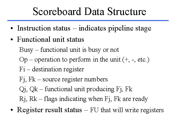
Scoreboard Data Structure • Instruction status – indicates pipeline stage • Functional unit status Busy – functional unit is busy or not Op – operation to perform in the unit (+, -, etc. ) Fi – destination register Fj, Fk – source register numbers Qj, Qk – functional unit producing Fj, Fk Rj, Rk – flags indicating when Fj, Fk are ready • Register result status – FU that will write registers
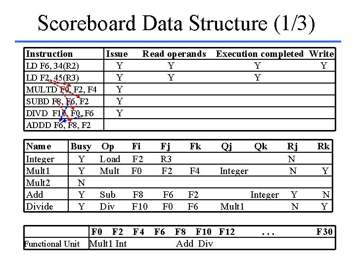
Scoreboard Data Structure (1/3) Instruction Issue LD F 6, 34(R 2) Y LD F 2, 45(R 3) Y MULTD F 0, F 2, F 4 Y SUBD F 8, F 6, F 2 Y DIVD F 10, F 6 Y Read operands Y Y Execution completed Write Y Y Y ADDD F 6, F 8, F 2 Name Integer Mult 1 Mult 2 Add Divide Busy Y Y N Y Y Op Load Mult Fi F 2 F 0 Fj R 3 F 2 Fk Qj F 4 Integer Sub Div F 8 F 10 F 6 F 0 F 2 F 4 Functional Unit Mult 1 Int F 6 Qk Integer Mult 1 F 8 F 10 F 12 Add Div . . . Rj N N Rk Y N N Y Y F 30
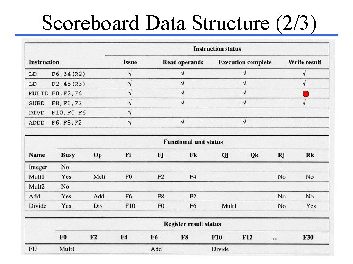
Scoreboard Data Structure (2/3)
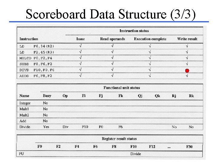
Scoreboard Data Structure (3/3)
Scoreboard Algorithm
Scoreboard Limitations • Amount of available ILP • Number of scoreboard entries – Limited to a basic block – Extended beyond a branch • Number and types of functional units – Structural hazards can increase with DS • Presence of anti- and output- dependences – Lead to WAR and WAW stalls
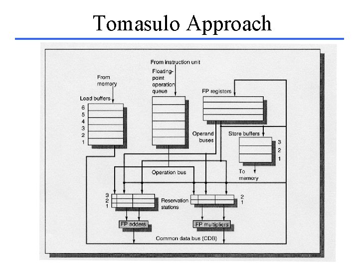
Tomasulo Approach • Another approach to eliminate stalls – Combines scoreboard with – Register renaming (to avoid WAR and WAW) • Designed for the IBM 360/91 – High FP performance for the whole 360 family – Four double precision FP registers – Long memory access and long FP delays • Can support overlapped execution of multiple iterations of a loop
Tomasulo Approach
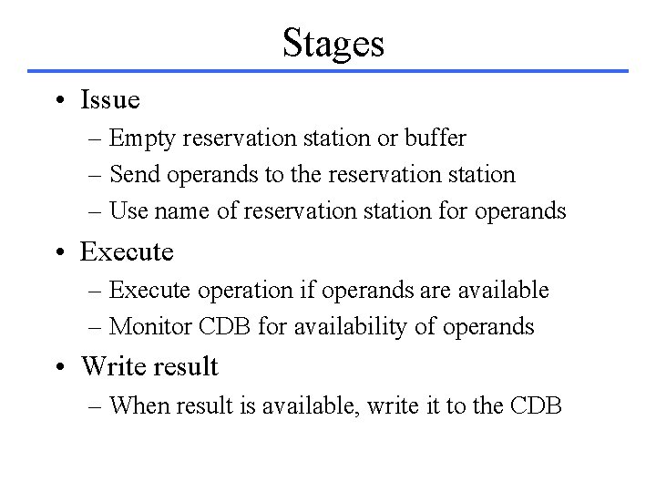
Stages • Issue – Empty reservation station or buffer – Send operands to the reservation station – Use name of reservation station for operands • Execute – Execute operation if operands are available – Monitor CDB for availability of operands • Write result – When result is available, write it to the CDB
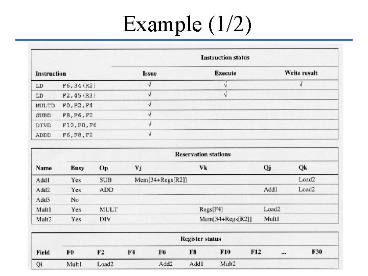
Example (1/2)
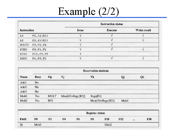
Example (2/2)
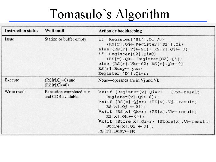
Tomasulo’s Algorithm
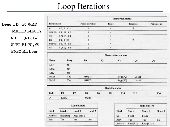
Loop Iterations Loop: LD F 0, 0(R 1) MULTD F 4, F 0, F 2 SD 0(R 1), F 4 SUBI R 1, #8 BNEZ R 1, Loop
- Slides: 40